Novel railway vehicle roof framework

A technology for rail vehicles and skeletons, applied in the field of rail vehicles, can solve the problems of large auxiliary work volume, etc., and achieve the effect of convenient installation and welding, and preventing excessive gaps.

Active Publication Date: 2020-09-22
安徽浦进轨道装备有限公司
View PDF5 Cites 0 Cited by
  • Summary
  • Abstract
  • Description
  • Claims
  • Application Information

AI Technical Summary

Problems solved by technology

[0003] When installing and welding the roof frame of rail cars, auxiliary tools are usually used to assist in order to avoid excessive ga

Method used


Image

  • Novel railway vehicle roof framework
  • Novel railway vehicle roof framework
  • Novel railway vehicle roof framework

Examples


Embodiment 1

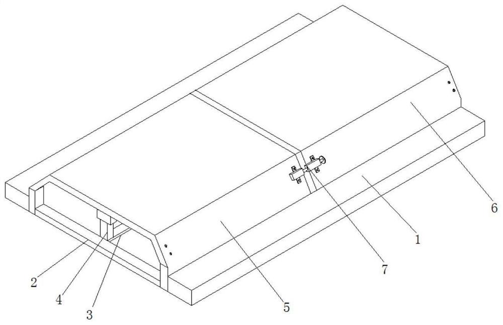
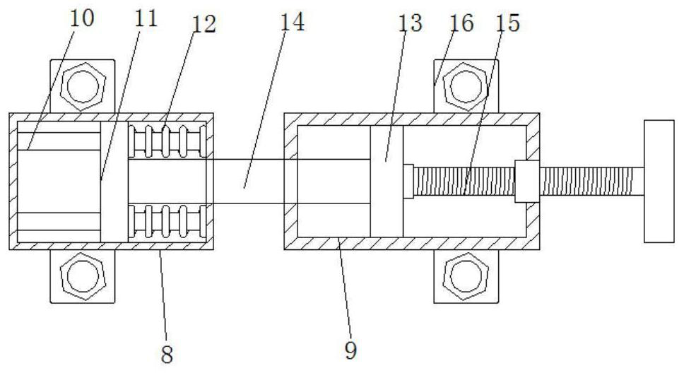
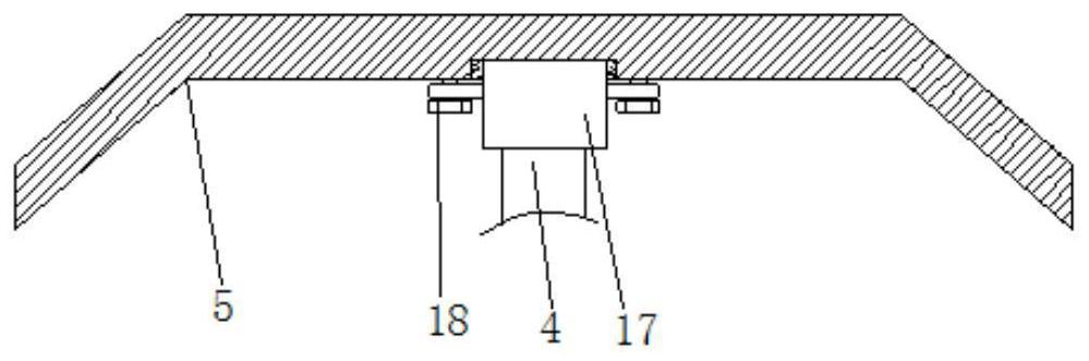
[0026] refer to Figure 1-3 , a new type of rail vehicle roof frame, including two mounting plates 1, the outer walls of the opposite sides of the two mounting plates 1 are fixed with connecting rods 2 through bolts, and the same fixing rod 2 is fixed between the two connecting rods 2 through bolts. Plate 3, the outer walls of the opposite sides of the two mounting plates 1 are fixed with slide rails by bolts, and the inner walls of the two slide rails are respectively slidably connected with the first top plate 5 and the second top plate 6, the first top plate 5 and the second top plate 6 The outer walls on both sides are provided with installation holes, the outer walls on both sides of the first top plate 5 and the second top plate 6 are provided with a connecting mechanism 7, and the support rods 4 are welded on the fixed plate 3. The connecting mechanism 7 includes the first connecting box 8 and the second connecting box. Two connecting boxes 9, the inner walls on both si...

Embodiment 2

[0028] refer to figure 1 , 2 and 4, a new rail vehicle roof frame, including two mounting plates 1, the outer walls of the opposite sides of the two mounting plates 1 are fixed with connecting rods 2 by bolts, and the two connecting rods 2 are fixed by bolts There is the same fixed plate 3, the outer walls of the opposite sides of the two mounting plates 1 are fixed with slide rails by bolts, and the inner walls of the two slide rails are respectively slidably connected with the first top plate 5 and the second top plate 6, the first top plate 5 and the second top plate Both sides outer walls of two top plates 6 are provided with installation holes, first top plate 5 and second top plate 6 both sides outer walls are all provided with connecting mechanism 7, are all welded with support bar 4 on the fixed plate 3, and connecting mechanism 7 comprises the first connection Box 8 and the second connection box 9, the inner walls on both sides of the first connection box 8 are fixed ...


PUM


Abstract

The invention discloses a novel railway vehicle roof framework. The novel railway vehicle roof framework comprises two mounting plates, connecting rods are fixed to the outer walls of the opposite sides of the two mounting plates through bolts, a same fixing plate is fixed between two connecting rods through bolts, sliding rails are fixed to the outer walls of the opposite sides of the two mounting plates through bolts, the inner walls of the two sliding rails are slidably connected to a first top plate and a second top plate correspondingly, mounting holes are formed in the outer walls of thetwo sides of the first top plate and the outer walls of the two sides of the second top plate, connecting mechanisms are arranged on the outer walls of the two sides of the first top plate and the outer walls of the two sides of the second top plate, supporting rods are welded to the fixing plates, and each connecting mechanism comprises a first connecting box and a second connecting box. The detachable connecting mechanism is installed between every two top plates, the two top plates are conveniently tensioned through adjusting bolts on the connecting mechanism, and the problem that a gap between the top plates is too large in the welding process is effectively solved.

Description

technical field [0001] The invention relates to the technical field of rail vehicles, in particular to a novel rail vehicle roof frame. Background technique [0002] Rail cars (including trailers, the same below) are the main means of transportation for construction departments such as railway equipment maintenance, overhaul, and infrastructure construction to perform tasks. There are two types of railcars: heavy and light. Those that can be withdrawn from the line by passengers at any time are called light railcars; those that cannot be withdrawn from the line by passengers at any time are called heavy railcars. [0003] Auxiliary tools are usually used to assist in the installation and welding of the rail car roof frame to avoid excessive gaps after the roof is welded. However, the existing auxiliary work volume is relatively large and is not suitable for any occasion. Contents of the invention [0004] The object of the present invention is to propose a novel rail vehi...

Claims


Application Information

Patent Timeline
IPC IPC(8): B61D17/12
CPCB61D17/12
Inventor 许超
Owner 安徽浦进轨道装备有限公司
Why Eureka
Try Eureka