RS-485 isolation circuit and safety barrier

A RS485, isolation circuit technology, applied in the field of signal transmission, can solve the problem of not supporting bidirectional communication differential signal isolation and so on

Inactive Publication Date: 2020-10-30
ZHEJIANG SUPCON TECH +1
View PDF12 Cites 6 Cited by
  • Summary
  • Abstract
  • Description
  • Claims
  • Application Information

AI Technical Summary

Problems solved by technology

[0004] However, the existing signal isolation schemes only support the isolation of one-way digit...

Method used


Image

  • RS-485 isolation circuit and safety barrier
  • RS-485 isolation circuit and safety barrier
  • RS-485 isolation circuit and safety barrier

Examples


Embodiment 1

[0046] Embodiment 1 of the present application provides an isolation circuit, which will be described in detail below with reference to the accompanying drawings.

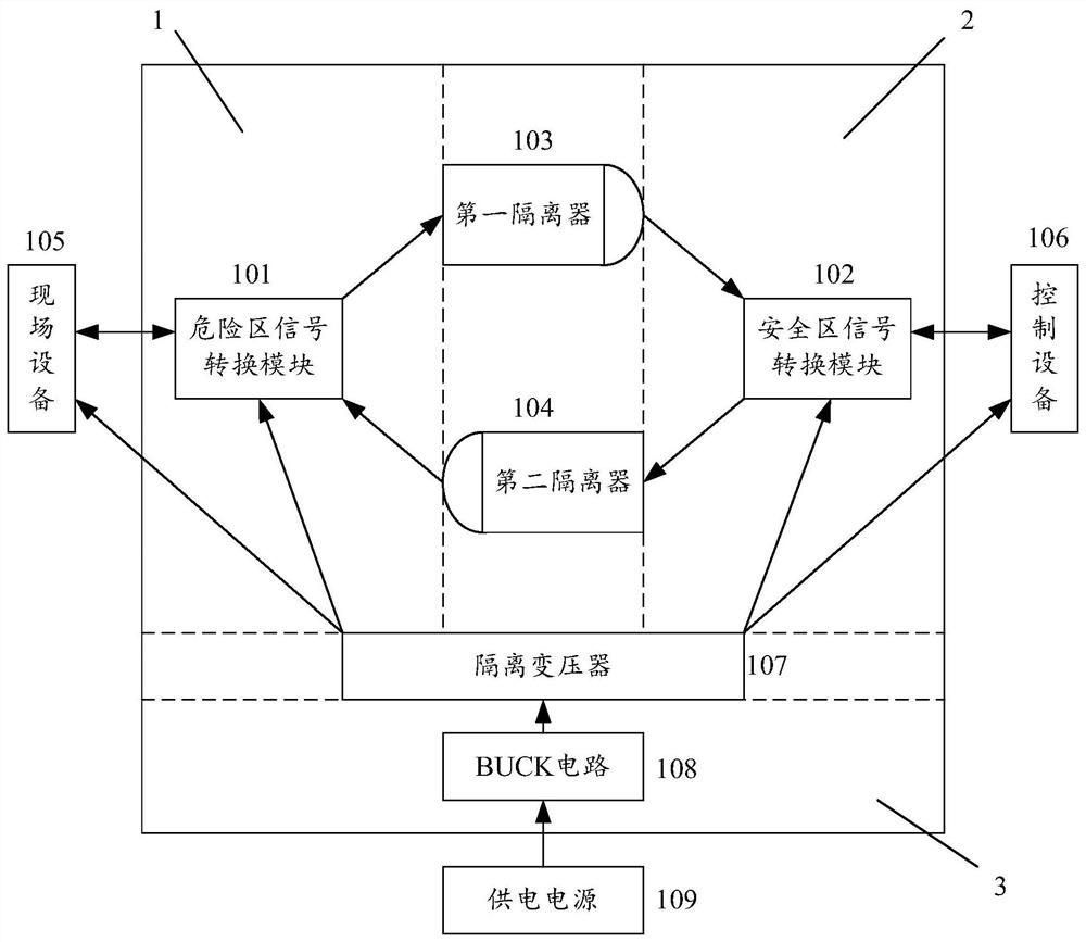
[0047] see figure 1 , which is a schematic diagram of an isolation circuit provided in an embodiment of the present application.

[0048] The isolation circuit includes: a dangerous area signal conversion module 101 , a safe area signal conversion module 102 , a first isolator 103 and a second isolator 104 .

[0049] In the figure, 1 represents the dangerous area, 2 represents the safe area, and 3 represents the power supply area.

[0050] The dangerous area signal conversion module 101 is located in the dangerous area, and the safe area signal conversion module 102 is located in the safe area.

[0051]Both the first isolator 103 and the second isolator 104 are located in the input-output isolation zone between the dangerous area and the safe area.

[0052] The first end of the hazardous area signal conversion m...

Embodiment 2

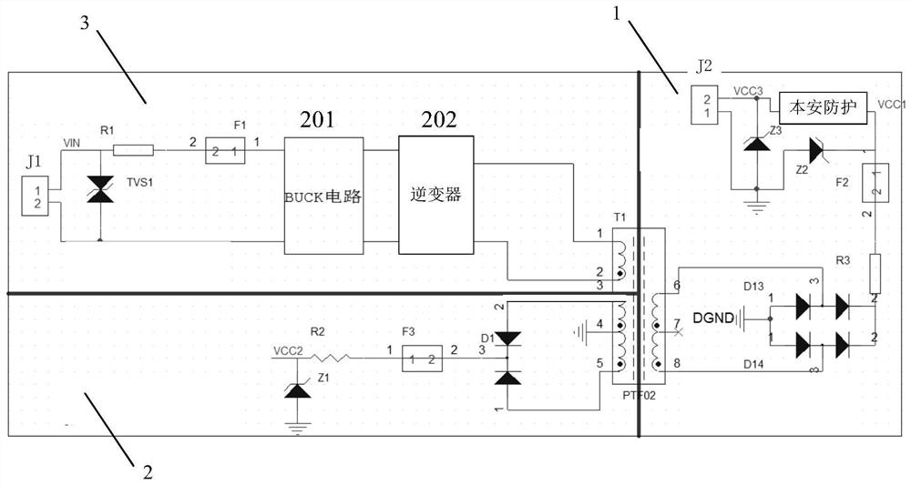
[0068] The above embodiments introduce an isolation circuit capable of realizing two-way communication between the field device and the control device, in order to meet the requirement of intrinsic safety. Protection devices are also included in the isolation circuits described below. The protective device includes: a resistor, a fuse, and a Zener diode; the first end of the resistor connected in series with the fuse is connected to the cathode of the Zener diode; the cathode of the Zener diode is used to connect to the field device; The anode of the Zener diode is grounded; the second end of the resistor connected in series with the fuse is used to connect the first end of the dangerous area signal conversion module. After adding protective devices in the isolation circuit, it can meet the requirements for intrinsically safe design.

[0069] Embodiment 2 provides yet another isolation circuit, which will be described in detail below with reference to the accompanying drawing...

Embodiment 3

[0083] Embodiment 3 of the present application provides yet another isolation circuit, which will be described in detail below with reference to the accompanying drawings.

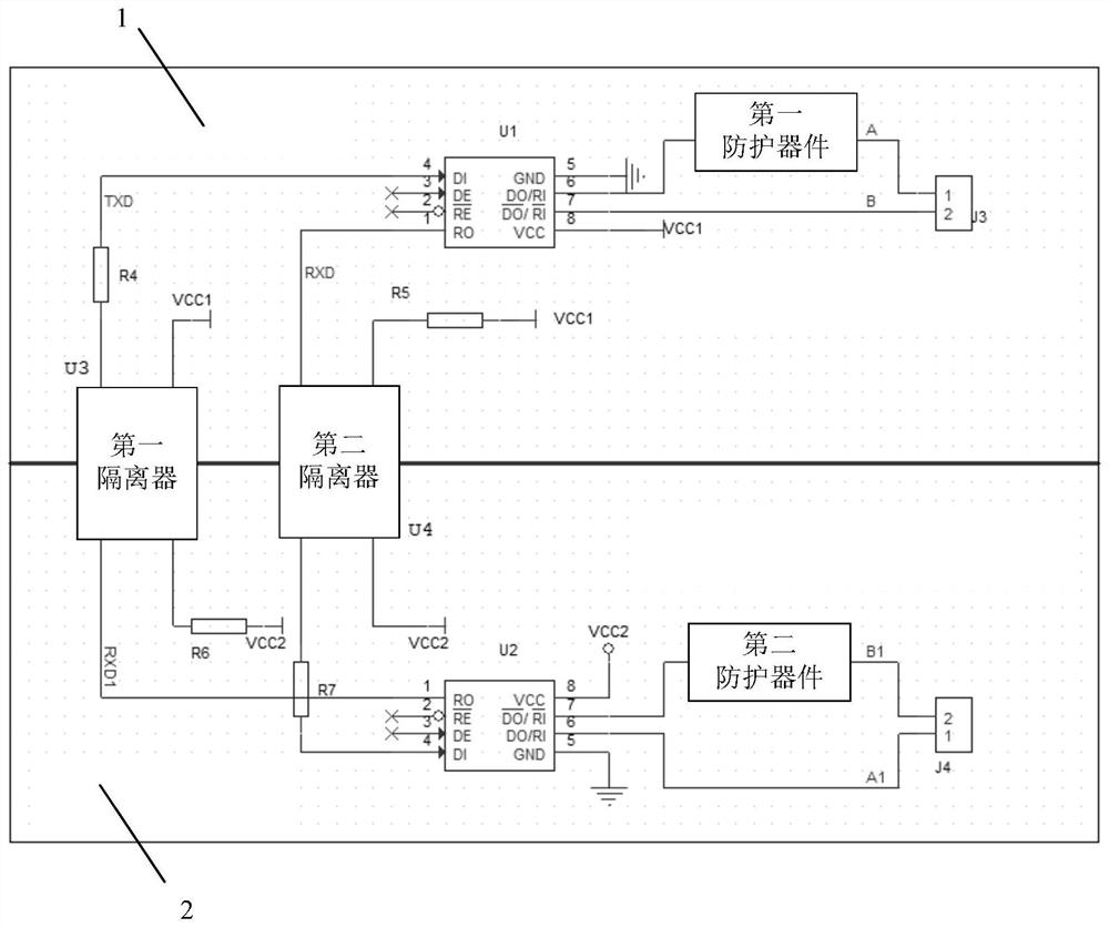
[0084] see image 3 , which is a schematic diagram of another isolation circuit provided in the embodiment of the present application.

[0085] The area shown in Figure 1 is a dangerous area, and the area shown in 2 is a safe area.

[0086] In the dangerous area, the J3 interface is used to connect with the field equipment, and the field equipment sends the first differential signal to the control equipment through the J3 interface.

[0087] Specifically, the first differential signal sent by the field device in the dangerous area is input through the J3 interface, the 1st pin of J3 is connected to the first differential signal A, and the 2nd pin of J3 is connected to the first differential signal B (A, B refer to the first differential signal differential pair), the first differential signal after input...


PUM


Abstract

The invention discloses an RS-485 isolation circuit and a safety barrier. The RS-485 isolation circuit comprises a danger zone signal conversion module, a safety zone signal conversion module, a firstisolator and a second isolator, wherein field equipment sends a first differential signal to control equipment, and the danger zone signal conversion module converts the first differential signal into a first digital signal; the first digital signal is sent to the safety zone signal conversion module through the first isolator; the safety zone signal conversion module restores the first digital signal into a first differential signal; the control equipment sends a second differential signal to the field equipment, and the safety zone signal conversion module converts the second differential signal into a second digital signal; the second digital signal is sent to the danger zone signal conversion module through the second isolator; and the danger zone signal conversion module restores thesecond digital signal into a second differential signal. The circuit can realize two-way communication between the field equipment and the control equipment, and intrinsic safety protection is added,so that intrinsic safety requirements in an industrial field environment can be met.

Description

technical field [0001] The present application relates to the technical field of signal transmission, in particular to an RS-485 isolation circuit and a safety barrier. Background technique [0002] Safety barriers, also known as safety energy limiters, are usually used in environments with flammable and explosive substances. [0003] Due to the complex environment of the industrial control site, when there are flammable and explosive substances, when the control equipment sends signals to the field equipment, it is necessary to use a safety barrier to isolate the safe area from the dangerous area. By using the safety barrier, the energy of the transmitted signal can be limited, so that the There is not enough energy to create a spark to cause an explosion. [0004] However, existing signal isolation solutions only support the isolation of unidirectional digital communication signals, but do not support the isolation of bidirectional communication differential signals. Co...

Claims


Application Information

Patent Timeline
IPC IPC(8): G05B19/418H03K19/0175
CPCG05B19/4185H03K19/0175Y02P90/02
Inventor 郭佛保黄萍薛斌徐德宏
Owner ZHEJIANG SUPCON TECH
Why Eureka
Try Eureka