Structure for connecting ends of two strips

A technology with ends and edges, applied in the direction of connection members, hose connection devices, applications, etc., can solve problems such as damage

Inactive Publication Date: 2003-08-20
OETIKER SCHWEIZ AG
View PDF6 Cites 0 Cited by
  • Summary
  • Abstract
  • Description
  • Claims
  • Application Information

AI Technical Summary

Problems solved by technology

Of course, DE 40 21 746 has the disadvantage that in order to avoid lateral detachment of the connecting fishplate located on both sides of the tongue, the engaging connection is provided with barb-like sharp corners, which makes it difficult to operate the corresponding clamping ring or clamping ring. no small risk of damage

Method used


Image

  • Structure for connecting ends of two strips
  • Structure for connecting ends of two strips
  • Structure for connecting ends of two strips

Examples


Embodiment Construction

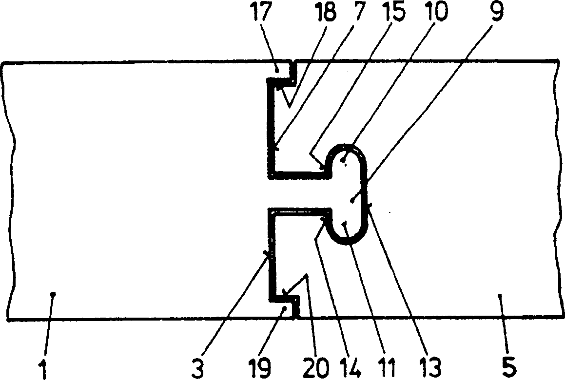
[0027] figure 1 A possible embodiment of a connection of two strips known from the prior art, eg suitable for latching a tubular clamp, is shown. The two end segments 1 and 5 of the strip are connected to each other along their common edge 3 or 7 . A stop or projection or tongue 9 is provided on one side 3, which comprises a fishtail-shaped part protruding laterally. This protrusion or tongue 9 consists of two such fishplates 10 and 11, wherein the tongue engages with the two fishplates in corresponding congruent grooves in the belt segment 5, which for the sake of simplicity No longer marked with a reference number. The tongue or projection 9 engages with the aid of the two fishplates or parts 10 and 11 from behind along the two parts 14 and 15 , viewed in the direction of the end edges, into a corresponding groove.

[0028] if figure 1 If the shown connection is stretched or upset, then the portion of the strip 5 behind the parts 14 and 15 will tend to come off from the ...


PUM


Abstract

The invention aims at improving the arrangement for connecting the edges of two end strips as described in DE-40 09 259. According to the invention, the improved arrangement for connecting the edges of a strip of a locking or compression ring enables enhanced tensile load. By comparison with the arrangement described in DE-40 09 259, the inventive connection has a tongue-like projecting part (21) exhibiting two interspaced lateral sections or brackets (23, 25, 27, 29) in the longitudinal direction of the strip. Said brackets engage in corresponding recesses located in the other section of the strip (5).

Description

technical field [0001] The present invention relates to a structure for connecting two strap ends, in particular a clip or tubular clamp with a structure and a compression ring or tight ring with a structure. Background technique [0002] For fastening tubular parts on corresponding peripheral regions of cylindrical profiles such as shafts or other pipes, so-called clamping rings are usually used. [0003] Collars with lugs, which are commonly used in practice, are not suitable in some cases. This is especially not the case, for example, when the dimensions of the space do not permit protruding ears. [0004] In these cases, such collars or compression rings prove suitable, either on the outside of the joint with shrink fit or press fit for fastening or by expanding the cylindrical profile to press the two tubes against each other . [0005] Such collars or compression rings are manufactured by sawing or molding or cutting ring segments from a tube of the desired diameter...

Claims


Application Information

Patent Timeline
IPC IPC(8): F16B2/08F16L33/02
CPCF16L33/02Y10T24/1463Y10T24/148Y10T24/1457
Inventor H·奥蒂克
Owner OETIKER SCHWEIZ AG
Why Eureka
Try Eureka