A speed-limiting tooling for forming cone parts for a plate rolling machine and a cone forming method

A plate rolling machine and tooling technology, applied in the field of mechanical processing, can solve problems such as increased labor intensity, low production efficiency, and poor stability of workpiece dimensional accuracy, and achieve the effects of reducing safety hazards, improving production efficiency, and reducing the difficulty of correction

Active Publication Date: 2022-05-17
SICHUAN AEROSPACE LONG MARCH EQUIP MFG CO LTD
View PDF0 Cites 0 Cited by
  • Summary
  • Abstract
  • Description
  • Claims
  • Application Information

AI Technical Summary

Problems solved by technology

[0002] For the processing of some cone parts, especially those involving aerospace or related industries, due to the structural characteristics of the cone parts, ordinary processing methods are usually difficult to meet the needs.
[0003] For example, the use of segmented stamping forming does not require segmental stamping on large molds, so that the profiles of each segment cannot be completely matched, and the straightness of the busbar is poor, making it difficult to ensure good quality requirements. At the same time, the installation and related debugging of the mold It is also extremely cumbersome and increases labor intensity;
[0004] However, the plate rolling machine is used for rolling and forming. The ordinary plate rolling machine does not have a speed limiting device. In this way, in the actual processing, the operator needs to continuously adjust the speed of the upper and lower ends by tapping with bare hands or with a hammer. This process is very harmful to the operator. High skill requirements indirectly increase the production cost. At the same time, frequent adjustments to the speed and the shape of the plate to be rolled also lead to low production efficiency and poor stability of the dimensional accuracy of the processed workpiece.
At the same time, because the operator is too close to the equipment, there is also a potential safety hazard of accidents.

Method used


Image

  • A speed-limiting tooling for forming cone parts for a plate rolling machine and a cone forming method
  • A speed-limiting tooling for forming cone parts for a plate rolling machine and a cone forming method
  • A speed-limiting tooling for forming cone parts for a plate rolling machine and a cone forming method

Examples


Embodiment Construction

[0033] In order to make the purpose, technical solutions and advantages of the present invention clearer, the present invention will be further described in detail below in conjunction with the examples and accompanying drawings. As a limitation of the present invention.

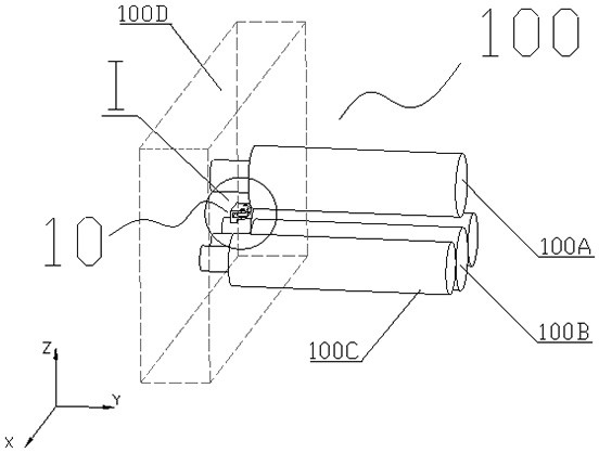
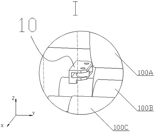
[0034] In some embodiments, a speed-limiting tool for forming cone parts for a plate rolling machine is installed on figure 1 On the plate bending machine 100 shown, the plate rolling machine 100 is used to process Figure 5 and Figure 6 The plate 200 to be rolled is shown. The plate rolling machine 100 may be a commonly used three-axis plate rolling machine or a four-axis plate rolling machine, and a four-axis plate rolling machine is used as an example below.

[0035] Such as figure 1 As shown, for the convenience of expression, it is assumed that the space has an XYZ coordinate system including the X axis, the Y axis and the Z axis, and the X axis, the Y axis and the Z axis are perpendicular to each ...


PUM


Abstract

The invention discloses a speed-limiting tool for forming cone parts for a plate rolling machine and a method for forming the cone. The speed-limiting tool is processed on one side of the frame body of the plate rolling machine, and the speed-limiting tool is provided, including a tool body, a pin Shafts, speed limiting and bearings. During processing, place the plate to be rolled between the upper roller and the lower roller, and keep the side of the small head of the plate to be rolled in contact with the speed-limiting peripheral surface. When the plate rolling machine is started, when the plate to be rolled moves continuously along the speed-limiting axis , the frictional force will be generated between the plate to be coiled and the speed limit, so that the speed of the side of the plate to be coiled contacting the speed limit will be slower than the speed of the plate to be rolled away from the side away from the speed limit, so that the two opposite sides of the plate to be coiled will form a stable The speed difference ensures that the axis of the rolled cone is always centripetal and parallel to the roller axis, so as to achieve the purpose of forming the cone.

Description

technical field [0001] The invention relates to the field of mechanical processing, in particular to a speed-limiting tool for forming cone-shaped parts for a plate rolling machine and a method for forming the cone. Background technique [0002] For the processing of some cone parts, especially those involving aerospace or related industries, due to the structural characteristics of the cone parts, ordinary processing methods are usually difficult to meet the needs. [0003] For example, the use of segmented stamping forming does not require segmental stamping on large molds, so that the profiles of each segment cannot be completely matched, and the straightness of the busbar is poor, making it difficult to ensure good quality requirements. At the same time, the installation and related debugging of the mold It is also extremely cumbersome and increases labor intensity; [0004] However, the plate rolling machine is used for rolling and forming. The ordinary plate rolling m...

Claims


Application Information

Patent Timeline
Patent Type & Authority Patents(China)
IPC IPC(8): B21D5/14
CPCB21D5/14
Inventor 凃强王妮罗成李小驹邓成旭胡国平张洪斌杜娟王洁谢玲
Owner SICHUAN AEROSPACE LONG MARCH EQUIP MFG CO LTD
Why Eureka
Try Eureka