An intelligent control hydraulic tool

A hydraulic tool, intelligent control technology, applied in the direction of manufacturing tools, punching machines, presses, etc., can solve the problems of poor replacement performance, large processing head limitations, poor response of the pressure relief mechanism, etc., to achieve stable structure of the pressure relief mechanism, Improve the effect of using intelligence and controllability

Active Publication Date: 2022-04-01
昆山盛世伟图电子科技有限公司
View PDF9 Cites 0 Cited by
  • Summary
  • Abstract
  • Description
  • Claims
  • Application Information

AI Technical Summary

Problems solved by technology

[0002] Hydraulic tools are tools that are more common in industrial applications. Its structure is usually such as the structure of a hydraulic tool disclosed in the invention patent of CN110107556A, including the fuselage and hydraulic head. The combined product is placed at the position of the hydraulic head to achieve pressing through the extension of the tool ejector rod, but the existing hydraulic tools have the following problems: 1. The degree of intelligence is not high. When riveting, some such as wheel panels are riveted 2. The processing heads of existing hydraulic tools have relatively large limitations, and The replacement performance is poor, and the processing uniformity is high. 3. The response of the pressure relief mechanism is poor after reaching the pressure value

Method used


Image

  • An intelligent control hydraulic tool
  • An intelligent control hydraulic tool
  • An intelligent control hydraulic tool

Examples


Embodiment 1

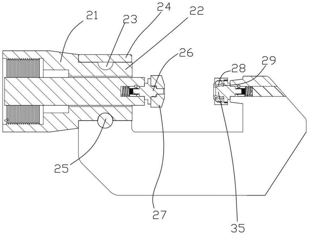
[0031]The fixed head includes a C-shaped head, one end of the C-shaped head is provided with a ring sleeve 24, and the inner wall of the ring sleeve 24 is provided with a perforation, and the perforation corresponds to the inner ring 23 and is inserted with a fixing pin 25, The ring sleeve 24 and the inset ring 23 of the installation part 22 are limited by the fixing pin 25. The output end of the oil cylinder 2 is connected with a punch 26, and the punch 26 is covered with an elastic pad 27, and the punch 26 wears Through the elastic pad 27, the other end of the C-shaped head is provided with a die, and the die includes an equal segment block 28 arranged in a trisecting ring, and the outer portion of the equal segment block 28 is provided with an elastic ring. Equally divided block 28 is provided with a limiter 35, the bottom of the limiter 35 is provided with a ring groove, the bottom of the equalized block 28 is provided with a spherical block 29, and the spherical block 29 i...

Embodiment 2

[0033] Be set as movable head, movable head then comprises square bar 36, and square bar 36 one ends are provided with ring sleeve 24, and the other end is then covered with movable block, die is installed on the movable block, punch 26 concaves of the present embodiment The mode of mold installation is the same as that of Embodiment 1, all of which are connected by threads. The lower part of the movable block is provided with a locking groove 37, and a locking pin 38 is inserted in the locking slot 37. The locking pin 38 is arranged on a spring for positioning. The position of the movable block and the square rod 36 can further process thicker plates, improving the applicability of use.

[0034] In addition, the riveting head can also be replaced with a punching head, only need to change the mould, and because the pressure in the hydraulic tool processing process is relatively large, after the die and the punch 26 connected by the thread receive the force, it will cause seriou...


PUM


Abstract

The invention proposes an intelligent control hydraulic tool, which includes a casing, and a hydraulic pump, an oil bag and an oil cylinder are arranged in the casing, and the hydraulic pump is connected with the oil bag, and pumps oil into the inlet of the oil cylinder. Oil end, the output end of the oil cylinder is connected with a working head, the oil return end of the oil cylinder is provided with a pressure relief mechanism, the bottom of the casing is provided with a control module, and the control module is used to record the maintenance scene and call the maintenance mode , the intelligent control hydraulic tool is equipped with a processing head that can be changed in a variety of ways, and the structure of the riveting hole is stable, and an intelligent control module is set, which can adjust the riveting parameters according to the actual situation and improve the intelligence of use; the set pressure relief mechanism has a stable structure, Increased controllability.

Description

technical field [0001] The invention relates to the field of hydraulic tools, in particular to intelligent control hydraulic tools. Background technique [0002] Hydraulic tools are tools that are more common in industrial applications. Its structure is usually such as the structure of a hydraulic tool disclosed in the invention patent of CN110107556A, including the fuselage and hydraulic head. The combined product is placed at the position of the hydraulic head to achieve pressing through the extension of the tool ejector rod, but the existing hydraulic tools have the following problems: 1. The degree of intelligence is not high. When riveting, some such as wheel panels are riveted 2. The processing heads of existing hydraulic tools have relatively large limitations, and The replacement performance is poor, and the processing unitary is relatively high. 3. After reaching the pressure value, the response of the pressure relief mechanism is poor. Contents of the invention ...

Claims


Application Information

Patent Timeline
Patent Type & Authority Patents(China)
IPC IPC(8): B21D39/02B30B1/32B30B15/04B30B15/02B30B15/16B30B15/22B30B15/26
CPCB21D39/021B30B1/32B30B15/047B30B15/02B30B15/166B30B15/22B30B15/26
Inventor 李志强黎俊凯杨超靳丽萍
Owner 昆山盛世伟图电子科技有限公司
Why Eureka
Try Eureka