Stamping device for hardware fitting machining and using method

A technology of stamping equipment and accessories, which is applied in the field of stamping equipment for processing hardware accessories, can solve the problems of low processing efficiency and achieve the effect of improving processing efficiency and processing accuracy

Pending Publication Date: 2020-11-03
嘉兴市光炬五金科技有限公司
16 Cites 1 Cited by

AI-Extracted Technical Summary

Problems solved by technology

[0003] Ring fasteners are a kind of hardware. The traditional processing of ring fasteners uses equipment for stamping, but it...

Method used

Open large cylinder 62 and push wheel mold 63 and rush in punching groove 2, realize the stable stamping of steel band.
Wherein, what described driver 44 adopted is belt linkage mechanism, and transmission is comparatively stable.
[00...

Abstract

The invention discloses a stamping device for hardware fitting machining and a using method. The stamping device comprises a machining table, a stamping groove and a pressing device, wherein the stamping groove is formed in the surface of the machining table, the pressing device is arranged at the position, located above the stamping groove, of the top of the machining table, inner die plates aresymmetrically arranged in the stamping groove, the inner die plates are elastically and rotationally connected with the inner wall of the stamping groove through torsion springs, touch mechanisms forelastically stretch-out and draw-back touch are arranged at the positions, corresponding to the inner die plates, of the bottom of the machining table, a feeding mechanism for rolling extruding guiding is arranged on the side, away from the pressing device, of the top of the machining table, and a cutting mechanism for pneumatic quick punching is arranged at the end of the feeding mechanism. According to the stamping device for hardware fitting machining, an annular pressing mode is adopted, and the inner die plates capable of movable rotating are matched, so that the annular extrusion is carried out on a steel belt, tight annular wrapping is guaranteed, and the one-step forming effect is achieved; and meanwhile, a linkage mechanism is triggered, so that the whole machining process is coherent, and the machining efficiency and the machining precision are improved.

Application Domain

Metal-working feeding devicesPositioning devices +1

Technology Topic

Processing accuracyTorsion spring +4

Image

  • Stamping device for hardware fitting machining and using method
  • Stamping device for hardware fitting machining and using method
  • Stamping device for hardware fitting machining and using method

Examples

  • Experimental program(1)

Example Embodiment

[0027] The technical solutions in the embodiments of the present invention will be clearly and completely described below in conjunction with the accompanying drawings in the embodiments of the present invention. Obviously, the described embodiments are only a part of the embodiments of the present invention, rather than all the embodiments. Based on the embodiments of the present invention, all other embodiments obtained by those of ordinary skill in the art without creative work shall fall within the protection scope of the present invention.
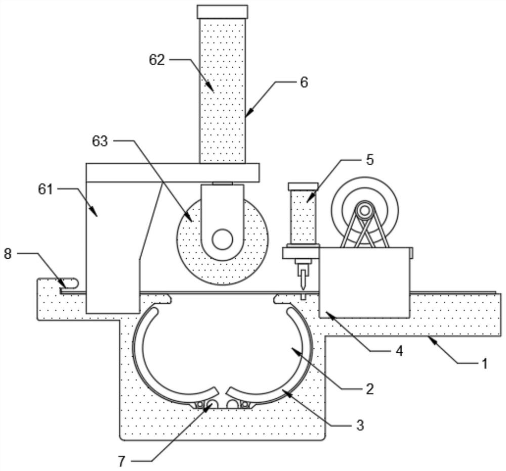
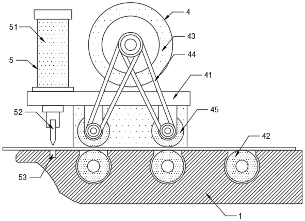
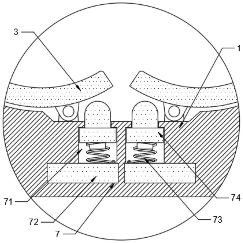
[0028] See figure 1 with Figure 4 , The punching equipment for processing hardware accessories in the figure includes a processing table 1, a punching groove 2 and a pressing device 6. The surface of the processing table 1 is provided with a punching groove 2, and the top of the processing table 1 is located at the punching groove 2. A pressing device 6 is installed on the upper side. The punching groove 2 is provided with an inner template 3 symmetrically, and the inner template 3 is elastically connected to the inner wall of the punching groove 2 through a torsion spring. The bottom of the processing table 1 is installed at the corresponding position of the inner template 3 There is a touch mechanism 7 with elastic telescopic touch. The top of the processing table 1 is equipped with a rolling and squeezing-guided feeding mechanism 4 on the side away from the pressing device 6, and the end of the feeding mechanism 4 is installed with a pneumatic fast punching cutting material Mechanism 5, and the material cutting mechanism 5 is electrically connected to the touch control mechanism 7. The processing table 1 is provided with an undercut groove 8 at the end, and the undercut groove 8 is installed in the undercut groove 8 with a second electrically connected to the pressing device 6 Micro switch 81.
[0029] The conveying steel belt is stably guided by the feeding mechanism 4. When the end of the steel belt is inserted into the undercut groove 8 and the second micro switch 81 is touched, the pressing device 6 presses the steel belt, and the steel belt is pressed into the punching groove 2 inside, and the steel belt is gradually attached to the inner template 3 to realize the annular extrusion of the steel belt. Through the touch of the touch mechanism 7, the cutting mechanism 5 cuts the steel belt, and then the pressing device 6 The reset completes a process of processing and realizes the automatic replacement and stable stamping of the ring steel belt.
[0030] See figure 2 The feeding mechanism 4 includes a bracket 41, a guide wheel 42, a motor 43, a transmission 44, and a pressure wheel 45. The bracket 41 is fixedly connected to the processing table 1, and the surface of the processing table 1 is rotatably installed with the guide wheels 42. A pressure wheel 45 is rotatably installed on the bottom surface of the bracket 41 at a corresponding position of the guide wheel 42, a motor 43 is installed on the top of the bracket 41, and the motor 43 is drivingly connected to the pressure wheel 45 through a transmission 44.
[0031] The opening motor 43 is driven by the transmission 44 to rotate the pressing wheel 45, and the steel belt is pressed between the pressing wheel 45 and the guide wheel 42, and is steadily guided forward to realize automatic feeding and feeding.
[0032] Wherein, the transmission 44 adopts a belt linkage mechanism, and the transmission is relatively stable.
[0033] Wherein, the outer surfaces of the guide wheel 42 and the pressure wheel 45 are fixedly bonded with a rubber layer, and the friction factor of the rubber layer is relatively large, so that the guide wheel 42 and the pressure wheel 45 can stably convey the steel belt.
[0034] See figure 2 The cutting mechanism 5 includes a small air cylinder 51, a punching knife 52, and a knife groove 53, the small air cylinder 51 is installed at the end of the bracket 41 of the feeding mechanism 4, and a punching knife 52 is fixedly installed on the telescopic end of the small air cylinder 51, A knife groove 53 is formed on the surface of the worktable at a corresponding position of the punching knife 52.
[0035] The small cylinder 51 is turned on to quickly push the punching knife 52 to expand and contract, so that the punching knife 52 rushes into the knife groove 53 to break the steel belt, and complete the rapid cutting of the steel belt.
[0036] See figure 1 The pressing device 6 includes a support 61, a large cylinder 62, and a wheel mold 63. The support 61 is fixedly connected to the processing platform 1, and the surface of the support 61 is located at a position directly opposite to the punching groove 2 and a large cylinder 62 is installed. , And the output end of the large cylinder 62 is equipped with a wheel mold 63 that is structurally matched with the inner template 3.
[0037] The large cylinder 62 is turned on to push the wheel die 63 into the punching groove 2 to achieve stable punching of the steel belt.
[0038] See image 3 The touch mechanism 7 includes a telescopic groove 71, a first micro switch 72, a return spring 73, and a pressure column 74. The telescopic groove 71 is symmetrically opened at the bottom of the punching groove 2, and the telescopic groove 71 passes through a return spring 73. A pressure column 74 is elastically installed, a first micro switch 72 is installed at the bottom of the telescopic groove 71, and the first micro switch 72 is electrically connected to the material cutting mechanism 5.
[0039] When the steel strip is pressed into the punching groove 2, the inner template 3 is turned over, and the end of the inner template 3 presses the pressing column 74, so that the pressing column 74 overcomes the elastic force of the return spring 73 and touches the first micro switch 72 to complete the alignment. The drive control of the cutting mechanism 5 realizes automatic continuous processing.
[0040] The corners of the top port position of the punching groove 2 are all provided with rounded corners, so as to avoid that the corners of the top port position of the punching groove 2 are too sharp to cause scratches on the steel strip.
[0041] Steps:
[0042] 1) Pass the steel belt between the feeding mechanism 4, perform a limit guide, and open the feeding mechanism 4 to drive and guide the steel belt;
[0043] 2) Insert the end of the steel strip into the undercut groove 8 and touch the second micro switch 81, so that the feeding mechanism 4 stops the feeding drive, and the pressing device 6 is turned on at the same time;
[0044] 3) The large cylinder 62 drives the wheel die 63 to squeeze the steel strip downwards. The steel strip is pressed into the punching groove 2 and contacts the inner template 3, and the inner template 3 is pressed and turned over until the inner template 3 wraps the steel strip. Finish the extrusion on the outside of the wheel mold 63;
[0045] 4) Press to the bottom touch control mechanism 7, so that the pressing device 6 stops pressing, and the cutting mechanism 5 is turned on to punch and cut the steel strip, and then the pressing device 6 rises and resets to complete the processing;
[0046] 5) Remove the stamped hardware and proceed to the next processing flow.
[0047] It should be noted that in this article, relational terms such as first and second are only used to distinguish one entity or operation from another entity or operation, and do not necessarily require or imply one of these entities or operations. There is any such actual relationship or order between. Moreover, the terms "include", "include" or any other variants thereof are intended to cover non-exclusive inclusion, so that a process, method, article, or device that includes a series of elements includes not only those elements, but also includes Other elements of, or also include elements inherent to this process, method, article or equipment.
[0048] Although the embodiments of the present invention have been shown and described, those of ordinary skill in the art can understand that various changes, modifications, and substitutions can be made to these embodiments without departing from the principle and spirit of the present invention. And variations, the scope of the present invention is defined by the appended claims and their equivalents.

PUM

no PUM

Description & Claims & Application Information

We can also present the details of the Description, Claims and Application information to help users get a comprehensive understanding of the technical details of the patent, such as background art, summary of invention, brief description of drawings, description of embodiments, and other original content. On the other hand, users can also determine the specific scope of protection of the technology through the list of claims; as well as understand the changes in the life cycle of the technology with the presentation of the patent timeline. Login to view more.

Similar technology patents

Drilling equipment for self-adaptive track panel induction plate

PendingCN112453904AReduce auxiliary timeImprove machining accuracy and machining efficiency
Owner:CHINA RAILWAY CONSTR HEAVY IND +2

Heavy double-spindle integral ball valve whirlwind lathe

Owner:通用技术齐齐哈尔二机床有限责任公司

Intelligent five-axis control system and method thereof

PendingCN113848817ASolve the influence of secondary clamping errorImprove machining accuracy and machining efficiency
Owner:NORTHEASTERN UNIV

Classification and recommendation of technical efficacy words

  • Improve machining accuracy and machining efficiency

Method for preparing ceramic bond super-hard abrasive tool

ActiveCN101913122AImprove machining accuracy and machining efficiencyImprove self-sharpening ability
Owner:ADVANCED TECHNOLOGY & MATERIALS CO LTD +1

Catenary cantilever machining device

ActiveCN108583371ARealize fully automatic processingImprove machining accuracy and machining efficiency
Owner:CHINA CREC RAILWAY ELECTRIFICATION BUREAU GRP
Why Eureka
Try Eureka