Constructional engineering continuous steel bar cutting-off device

A technology for steel bar cutting and construction engineering, which is applied in the field of continuous steel bar cutting devices in construction engineering, can solve the problems of inability to realize continuous equidistant cutting of steel bars, poor continuity of cutting operation, etc., and achieve the effect of improving efficient cutting effect and continuous cutting

Inactive Publication Date: 2020-11-03
韦楚旺
View PDF1 Cites 2 Cited by
  • Summary
  • Abstract
  • Description
  • Claims
  • Application Information

AI Technical Summary

Problems solved by technology

Although the device can be used to cut off steel bars, the continuity of the cut-off operation is poor, and the effect of continuous and equidistant cut-off of steel bars cannot be realized. Therefore, a continuous steel bar cut-off device for construction engineering is now provided to solve the above technical problems

Method used


Image

  • Constructional engineering continuous steel bar cutting-off device
  • Constructional engineering continuous steel bar cutting-off device
  • Constructional engineering continuous steel bar cutting-off device

Examples


Embodiment 1

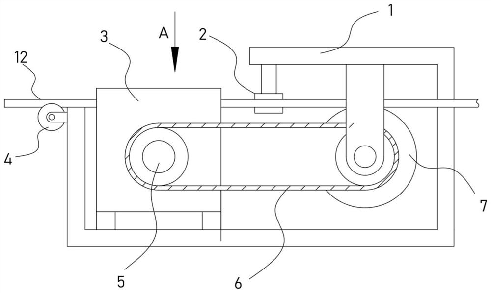
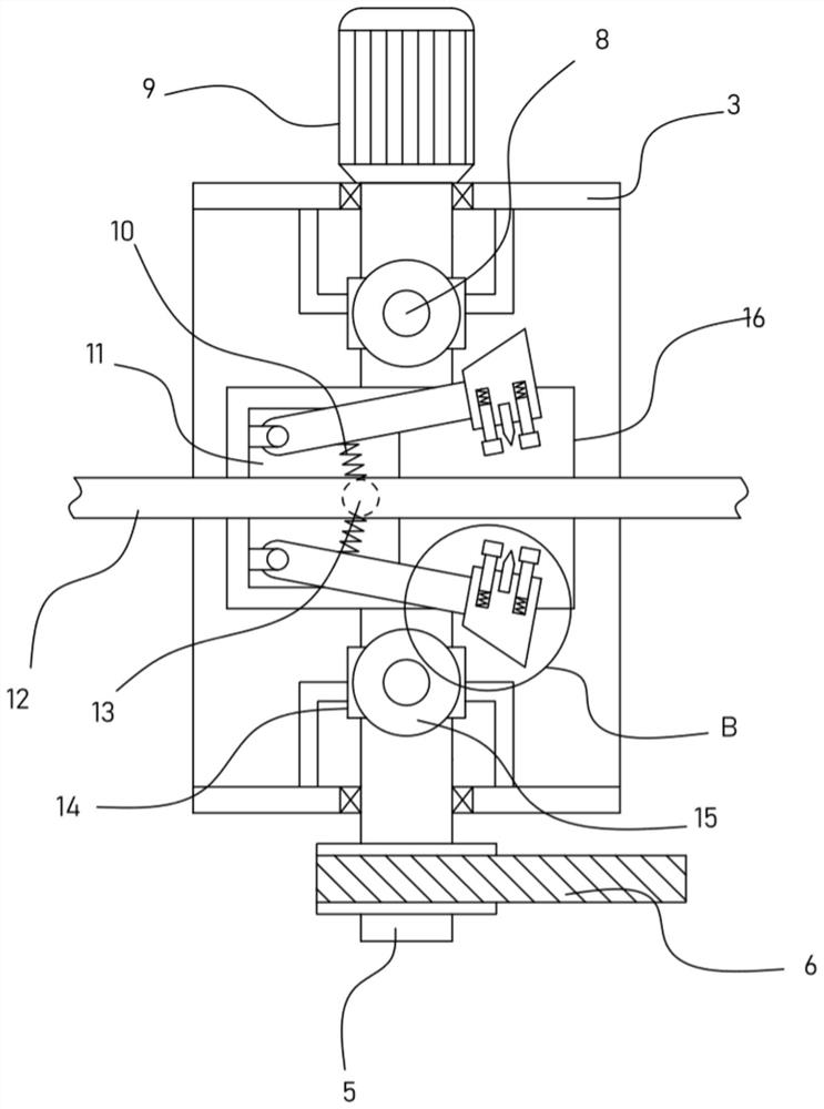
[0021] see Figure 1-3 , a continuous reinforcement cutting device for construction engineering, comprising a support frame 1, a fixed frame 3 is fixed on the support frame 1, a driving motor 9 is fixed on the fixed frame 3, and the output shaft of the driving motor 9 is coaxially fixed with a The drive shaft 5 in the fixed frame 3, the drive shaft 5 is sleeved with a rotating roller 16 fixed on the surface abutting the steel bar 12, the rotating roller 16 is provided with a groove 11, and two swing mechanisms are symmetrically arranged in the groove 11 , each swing mechanism is fixedly connected with a knife seat 22, and the knife seat 22 is provided with a cutting mechanism for cutting off the reinforcing bar 12.

[0022] When the steel bar 12 is cut off, the steel bar 12 is placed on the rotating roller 16, and the steel bar 12 is between the two swing mechanisms. The drive shaft 5 is driven to rotate by the drive motor 9 and then the rotating roller 16 is driven to rotate....

Embodiment 2

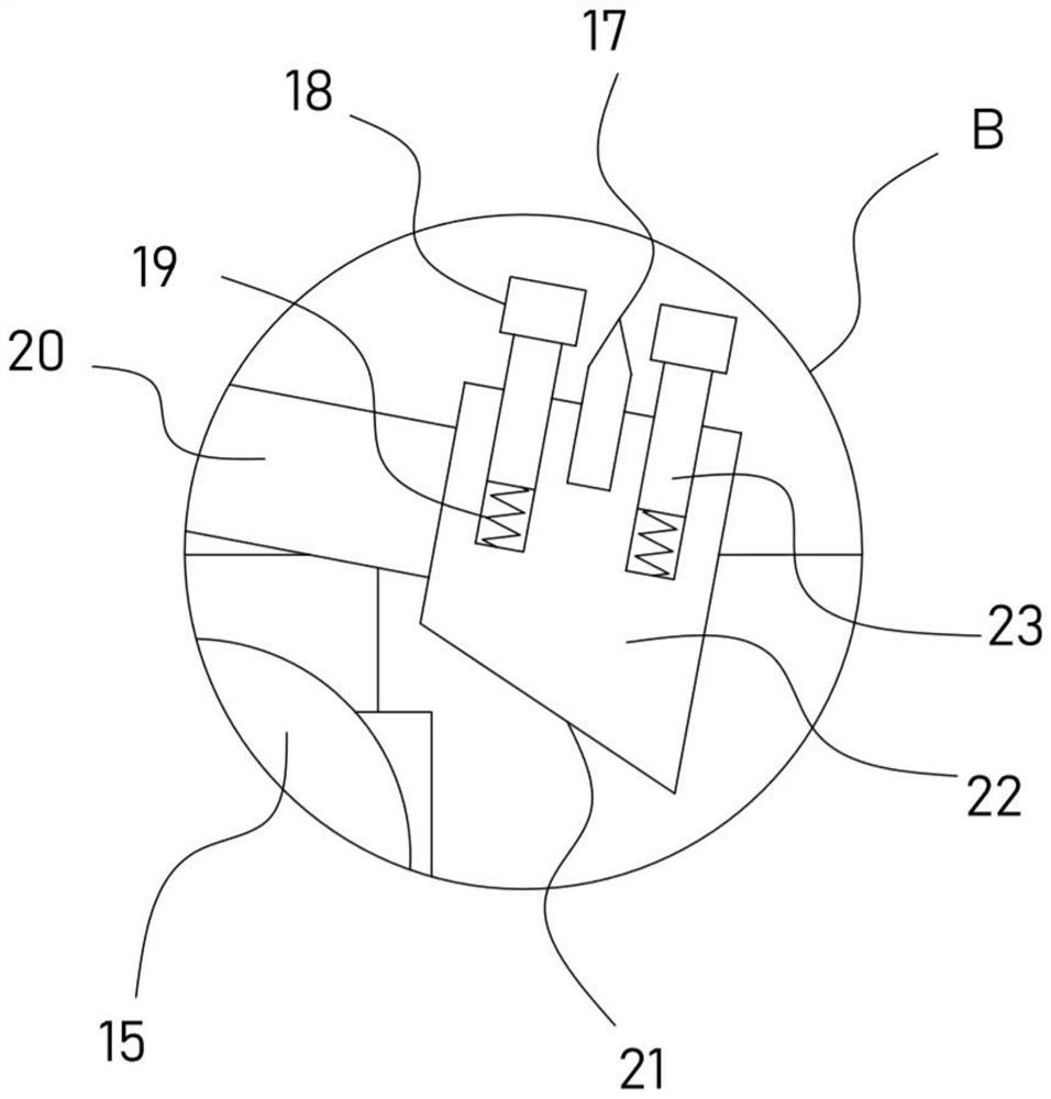
[0026] On the basis of Embodiment 1, in addition, the device is also provided with an elastic clamping mechanism including a sliding post 23 which is slidably embedded in the knife seat 22 and arranged parallel to the knife block 17. A telescopic spring 19 is fixed between them, and an arc plate 18 is fixed at the end of the sliding column 23 away from the knife seat 22 .

[0027] When the two swing rods 20 drive the knife block 22 close to the steel bar 12, the arc plate 18 on the knife block 22 contacts the steel bar 12 earlier than the knife block 17, and under the elastic resisting thrust of the telescopic spring 19, the two arc plates 18 first move The steel bar 12 is clamped and fixed, and then the telescopic spring 19 continues to compress, and the two knife blocks 17 will be cut off. The above operation ensures the short-term clamping and fixing effect of the steel bar 12 before cutting off, so that the cut-off position will not shift, effectively ensuring Cutoff mass ...


PUM


Abstract

The invention discloses a constructional engineering continuous steel bar cutting-off device, and relates to the technical field of building construction. The constructional engineering continuous steel bar cutting-off device comprises a supporting frame, a driving shaft extending into a fixing frame is coaxially fixed to an output shaft of a driving motor, a rotating roller with the surface abutting against steel bars is fixed to the driving shaft in a sleeving mode, and a tool apron is fixedly connected to each swing mechanism. A cutting-off mechanism used for cutting off the steel bars is arranged on each tool apron. According to the constructional engineering continuous steel bar cutting-off device, the arranged rotating roller is driven by the driving motor to rotate, thus the two swing mechanisms drive the cutting-off mechanisms to rotate, in the rotating process, the wedge faces of the tool aprons are in transmission with abutting transmission roller in an abutting mode intermittently, then two swing rods periodically get close to each other, and the effect of driving tool blocks in the cutting-off mechanisms to cut off the steel bars is achieved; and when the rotating roller rotates by a circle, the steel bars are conveyed leftwards by a certain length, the cutting-off mechanisms cut off the steel bars once, the equal-interval and continuous cutting-off effect of the steel bars is achieved, and the efficient cutting-off effect of the steel bars during building construction is greatly improved.

Description

technical field [0001] The invention relates to the technical field of building construction, in particular to a continuous steel bar cutting device for construction engineering. Background technique [0002] Building construction refers to the production activities in the implementation stage of engineering construction. It is the construction process of various buildings. It can also be said to be the process of turning various lines on the design drawings into real objects at designated locations. It includes basic engineering construction, main structure construction, roofing engineering construction, decoration engineering construction, etc. The place where the construction works is called "construction site" or "construction site", also called construction site. In the process of building construction, it is necessary to cut off the steel bars to be constructed. [0003] The authorized notification number is CN210586892 U, which discloses a construction steel bar cut...

Claims


Application Information

Patent Timeline
Patent Type & Authority Applications(China)
IPC IPC(8): B21F11/00B21F23/00
CPCB21F11/00B21F23/00
Inventor 韦楚旺
Owner 韦楚旺
Why Eureka
Try Eureka