
Annular workpiece inner hole chamfering device

A technology of chamfering device and annular workpiece, which is used in positioning devices, metal processing mechanical parts, manufacturing tools, etc. problem, to achieve the effect of high production efficiency, good chamfering uniformity, and reduced defective rate

Active Publication Date: 2020-11-03
ZHEJIANG LINIX MOTOR
View PDF13 Cites 1 Cited by
  • Summary
  • Abstract
  • Description
  • Claims
  • Application Information

AI Technical Summary

Problems solved by technology

[0002] Ring-shaped workpieces such as magnetic rings need to be chamfered at both ends of the inner hole, and the chamfering operation is mostly performed manually. It is difficult to ensure the angle of the inner hole chamfer and the uniformity of the inner hole chamfer, the rate of defective products is high, and the production efficiency is low.

Method used


Image

  • Annular workpiece inner hole chamfering device
  • Annular workpiece inner hole chamfering device
  • Annular workpiece inner hole chamfering device

Examples


Embodiment Construction

[0024] The present invention will be further described below according to the accompanying drawings and specific embodiments.

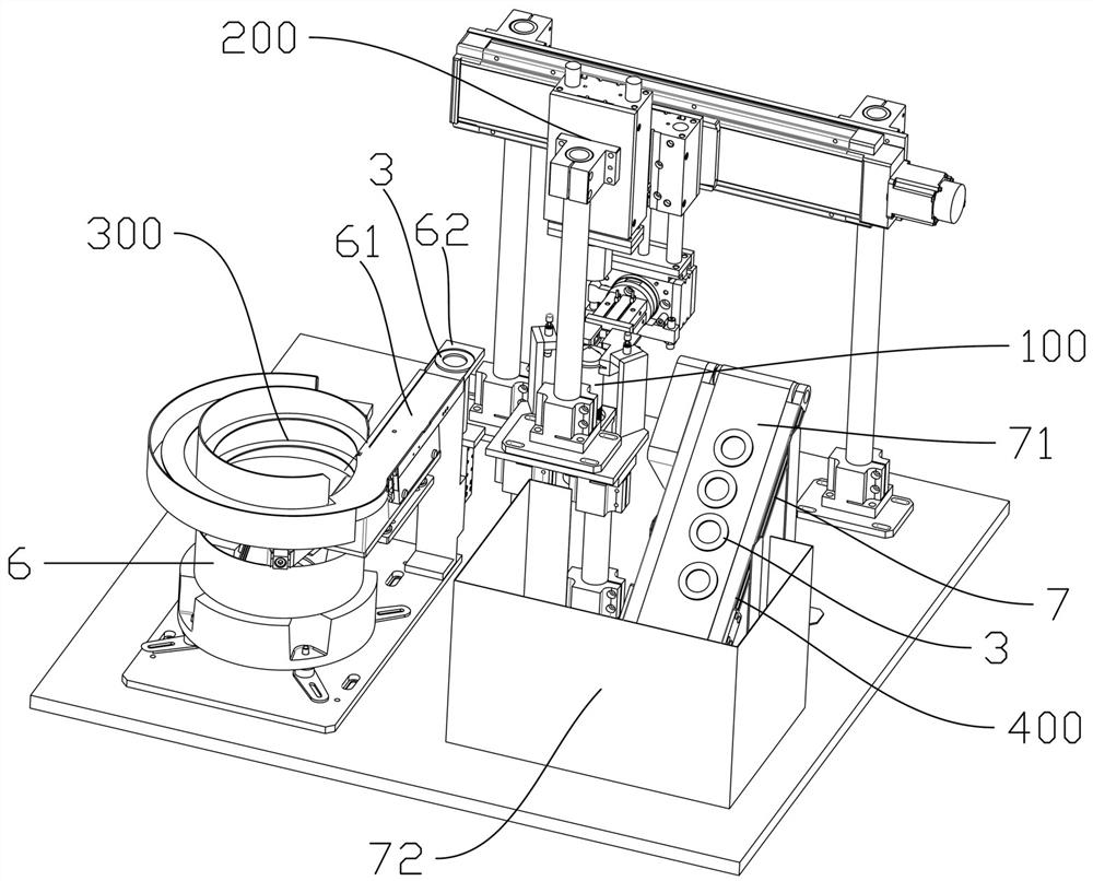
[0025] Depend on figure 1 As shown, a ring-shaped workpiece inner hole chamfering device of the present invention includes a chamfering mechanism 100 and a workpiece clamping and moving mechanism 200 arranged on the bottom plate 1, and the left and right sides of the chamfering mechanism 100 are respectively provided with a feeding mechanism 300 and a lower The material mechanism 400, the workpiece clamping and moving mechanism 200 is located at the rear side of the chamfering mechanism 100.

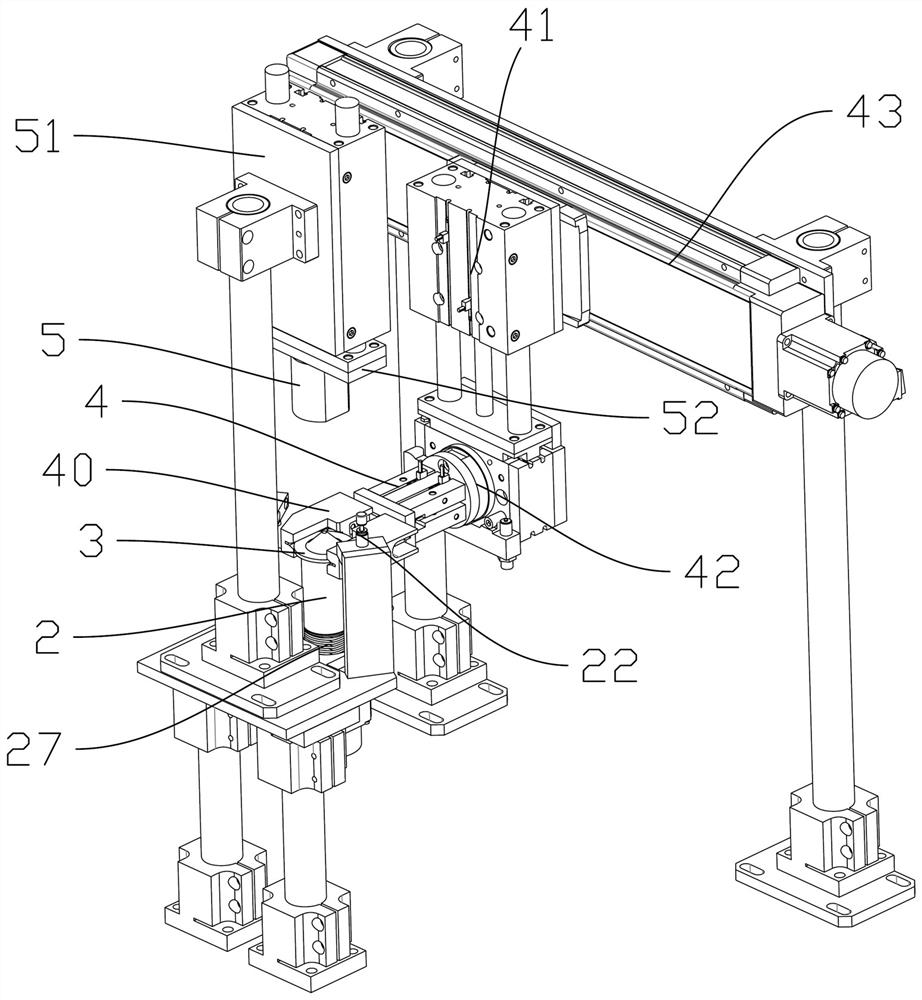
[0026] Depend on figure 2 , Figure 4 and Figure 5 As shown, the chamfering mechanism 100 includes a chamfering block 2 and a first drive mechanism 21 for rotating the chamfering block 2. The upper end of the chamfering block 2 is a chamfering end 20, which is a cone with a narrow top and a wide bottom. shaped structure. Wherein, the first driving mechani...


PUM


Abstract

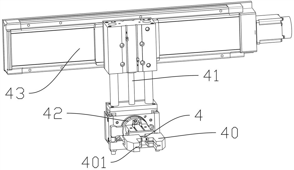
The invention relates to an annular workpiece inner hole chamfering device. The annular workpiece inner hole chamfering device comprises a chamfering mechanism and a workpiece clamping and moving mechanism which are arranged on a bottom plate, a feeding mechanism and a discharging mechanism are arranged on the left side and the right side of the chamfering mechanism respectively, the chamfering mechanism comprises a chamfering block and a first driving mechanism used for enabling the chamfering block to rotate, and the upper end of the chamfering block is a chamfering end. The chamfering end is of a conical structure with the narrow upper portion and the wide lower portion, the workpiece clamping and moving mechanism comprises a clamping jaw used for clamping a workpiece and capable of moving to the position above the chamfering block, a second driving mechanism used for enabling the clamping jaw to ascend and descend and a third driving mechanism used for enabling the clamping jaw tomove left and right, and the clamping jaw comprises clamping blocks oppositely arranged left and right. The opposite inner walls of the two clamping blocks are each provided with a positioning grooveused for limiting vertical movement of the workpiece. The chamfering device has the advantages that the chamfering angle and the chamfering uniformity can be guaranteed, the chamfering effect is improved, the defective rate is reduced, and the production efficiency is higher.

Description

technical field [0001] The invention relates to a chamfering device for the inner hole of an annular workpiece. Background technique [0002] Ring-shaped workpieces such as magnetic rings need to be chamfered at both ends of the inner hole, and the chamfering operation is usually performed manually. It is difficult to ensure the angle of the inner hole chamfer and the uniformity of the inner hole chamfer, the rate of defective products is high, and the production efficiency is low. . Contents of the invention [0003] The object of the present invention is to provide a chamfering device for the inner hole of an annular workpiece which can ensure the chamfering angle and the uniformity of the chamfering, improve the chamfering effect and reduce the defective rate, and has high production efficiency. [0004] In order to achieve the above object, the present invention adopts the following technical scheme: a device for chamfering the inner hole of an annular workpiece, incl...

Claims


Application Information

Patent Timeline
Patent Type & Authority Applications(China)
IPC IPC(8): B23D79/00B23Q3/08B23Q7/04
CPCB23D79/00B23Q3/08B23Q7/04Y02P70/10
Inventor 王辉陈永飞黄亮王佳栋
Owner ZHEJIANG LINIX MOTOR
Learn More