
Swash plate chamfering machine

A technology of chamfering machine and swash plate, which is applied in the field of chamfering machines, and can solve problems such as affecting product quality, difficult to control chamfering, and uneven chamfering

Pending Publication Date: 2018-02-16
JIANGSU CHUANGYUAN ELECTRON CO LTD
View PDF0 Cites 0 Cited by
  • Summary
  • Abstract
  • Description
  • Claims
  • Application Information

AI Technical Summary

Problems solved by technology

In this way, although the structure is simple, it is difficult to control the chamfering, and uneven chamfering is easy to occur, which directly affects the product quality.

Method used

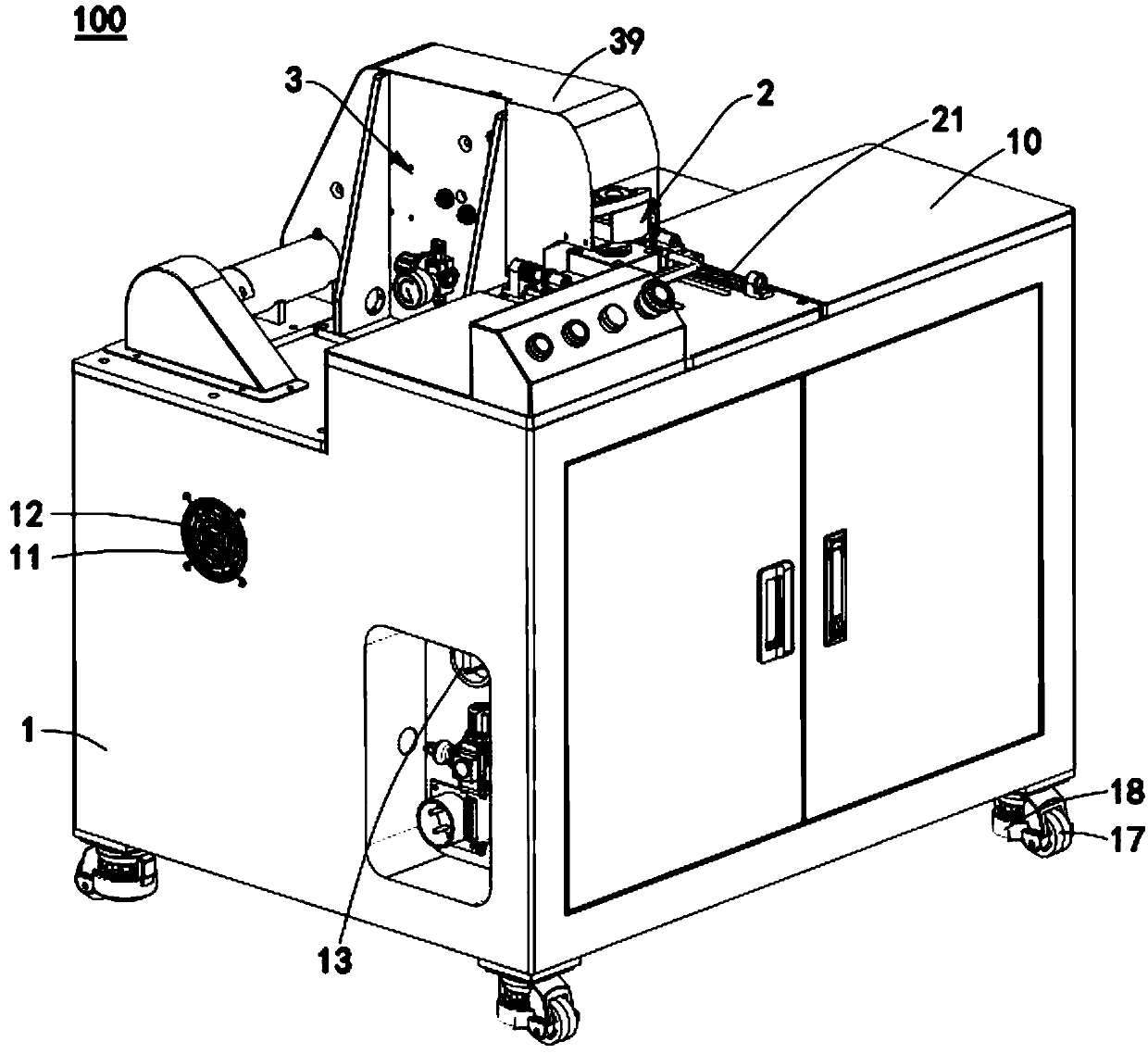
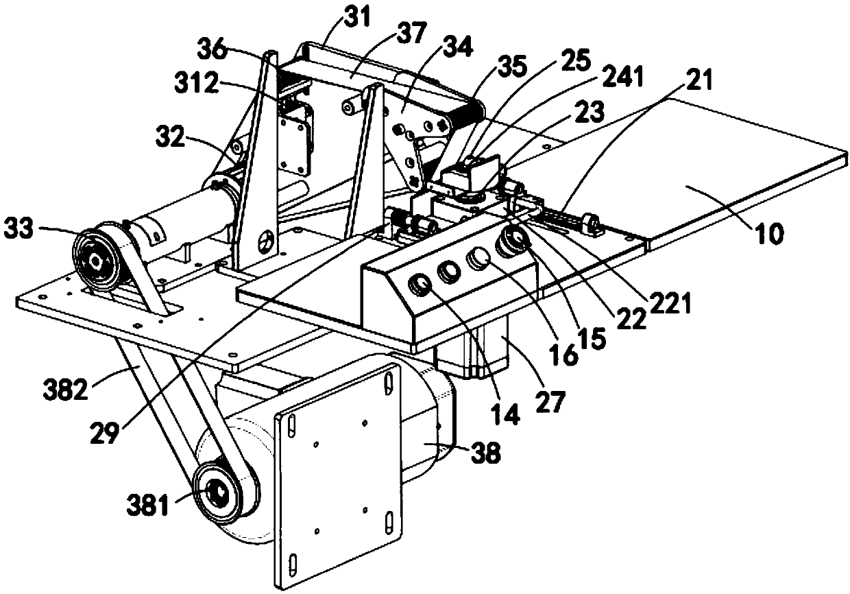
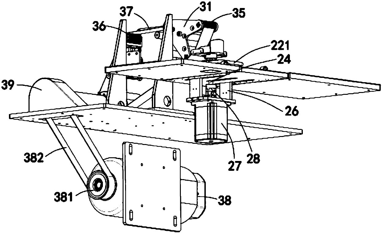

Image

  • Swash plate chamfering machine
  • Swash plate chamfering machine
  • Swash plate chamfering machine

Examples


Embodiment Construction

[0018] The following describes the embodiments of the present invention in detail. Examples of the embodiments are shown in the accompanying drawings, wherein the same or similar reference numerals indicate the same or similar elements or elements with the same or similar functions. The embodiments described below with reference to the accompanying drawings are exemplary, and are intended to explain the present invention, but should not be construed as limiting the present invention.

[0019] In the following description, in order to clearly demonstrate the structure and working mode of the present invention, many directional words will be used for description, but the words "upper", "lower", "left", "right", "front", "rear" "," "in", "out", "up", "down", "left", "right", "forward", "backward", "inward", "outward" and other words It should be understood as a convenient term, not a restrictive term.

[0020] Such as Figure 1 to Figure 3 As shown, the present invention provides a ...


PUM


Abstract

The invention provides a swash plate chamfering machine. The swash plate chamfering machine comprises a rack, a worktable arranged on the rack, a swash plate positioning rotary mechanism arranged on the worktable, and a chamfering mechanism arranged on one side of the swash plate positioning rotary mechanism. The chamfering mechanism comprises a supporting seat arranged on the worktable, an abrasive belt wheel, a belt wheel, tension wheel adjusting plates, a tension wheel, an adjusting block, a supporting wheel, an abrasive belt, a spring, a chamfering motor, a driving wheel and a chamfering synchronous belt, wherein the abrasive belt wheel is mounted at one end of the supporting seat; the belt wheel and the abrasive belt wheel are coaxial and are connected; the tension wheel adjusting plates are mounted at the other end of the supporting seat; the tension wheel is mounted on the tension wheel adjusting plates; the adjusting block is mounted on the supporting seat and can rotate aroundthe supporting seat; the supporting wheel is connected with the adjusting block; the sand belt is tensioned on the tension wheel, the abrasive belt wheel and the supporting wheel; the spring is arranged between the adjusting block and the supporting seat; the chamfering motor is mounted on the rack; the driving wheel is mounted at the output end of the chamfering motor; and the chamfering synchronous belt is tensioned on the belt wheel and the driving wheel. The edge of a swash plate is automatically chamfered through the swash plate chamfering machine, the chamfering effect is good, and chamfering is convenient and efficient.

Description

Technical field [0001] The invention relates to the technical field of chamfering machines, in particular to a swash plate chamfering machine. Background technique [0002] In the machinery industry, the swash plate is often involved. For the swash plate made of cast iron, when chamfering the swash plate in the circumferential direction, a swash plate chamfering machine is required. The existing swash plate chamfering machine usually drives the rotation mechanism to rotate by a motor, which drives the angle grinder to rotate to chamfer the swash plate. In this way, although the structure is simple, the chamfering is difficult to control, and uneven chamfering is easy to occur, which directly affects the product quality. Summary of the invention [0003] The technical problem solved by the present invention is to provide a swash plate chamfering machine with simple structure, good chamfering effect and high efficiency. [0004] In order to solve the above technical problems, the pr...

Claims


Application Information

Patent Timeline
IPC IPC(8): B24B21/00B24B21/20
CPCB24B21/002B24B21/20
Inventor 林强
Owner JIANGSU CHUANGYUAN ELECTRON CO LTD
Learn More