
Fixed chamfering device for valve production

A technology of chamfering devices and valves, which is applied in the direction of grinding drive devices, grinding machine parts, grinding/polishing equipment, etc. It can solve the problems of time-consuming and labor-intensive use of chamfering equipment, and the use of chamfering equipment is not flexible enough to achieve good results and chamfering. even angle effect

Inactive Publication Date: 2021-03-02
ANHUI ENDA VALVE MACHINERY CO LTD
View PDF0 Cites 0 Cited by
  • Summary
  • Abstract
  • Description
  • Claims
  • Application Information

AI Technical Summary

Problems solved by technology

[0004] The purpose of the present invention is to provide a fixed chamfering device for valve production to solve the problem that in the prior art, when chamfering, workers usually install the valve to be chamfered on a liftable and rotatable fixture seat, and then use chamfering The equipment performs chamfering. The existing chamfering equipment is not flexible enough to chamfer different angles, which is a time-consuming and laborious technical problem.

Method used


Image

  • Fixed chamfering device for valve production
  • Fixed chamfering device for valve production
  • Fixed chamfering device for valve production

Examples


Embodiment Construction

[0033] The technical solutions of the present invention will be clearly and completely described below in conjunction with the accompanying drawings. Apparently, the described embodiments are some of the embodiments of the present invention, but not all of them.

[0034] The components of the embodiments of the invention generally described and shown in the figures herein may be arranged and designed in a variety of different configurations. Accordingly, the following detailed description of the embodiments of the invention provided in the accompanying drawings is not intended to limit the scope of the claimed invention, but merely represents selected embodiments of the invention.

[0035] Based on the embodiments of the present invention, all other embodiments obtained by persons of ordinary skill in the art without making creative efforts belong to the protection scope of the present invention.

[0036] In the description of the present invention, it should be noted that the...


PUM


Abstract

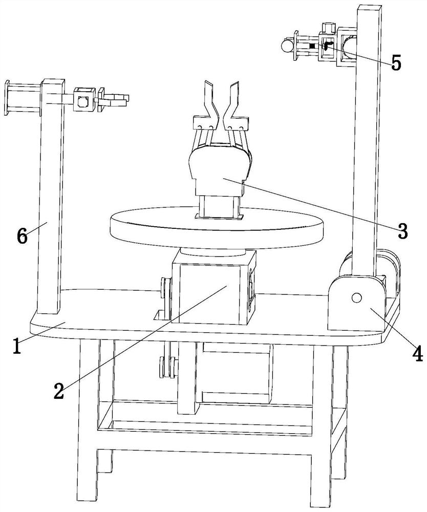
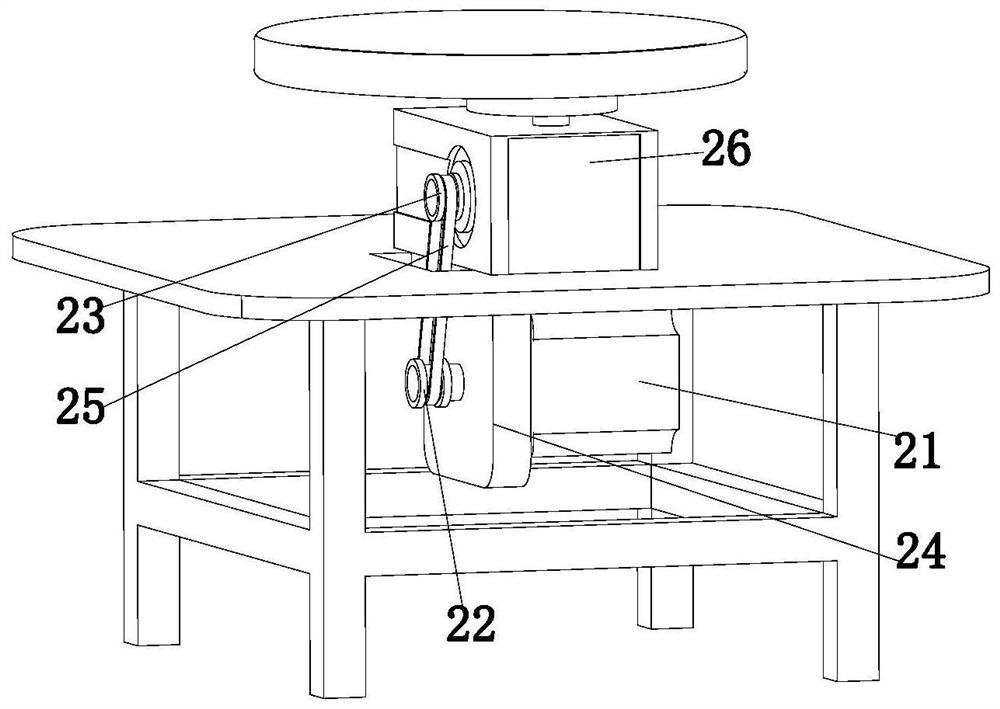
The invention discloses a fixed chamfering device for valve production and belongs to the technical field of valve processing. The fixed chamfering device for valve production comprises a workbench, arotating assembly, a fixing assembly, a lifting assembly, an extending assembly and an overturning assembly; the rotating assembly is arranged on the workbench; the fixing assembly is arranged at theworking end of the rotating assembly; the overturning assembly is arranged on the workbench; the overturning assembly is arranged on one side of the rotating assembly; the lifting assembly is arranged on the workbench; the lifting assembly is arranged on the other side of the rotating assembly; and the extending assembly is arranged at the working end of the lifting assembly. The steps of fixing,rotating, overturning and the like can be conducted on a valve through matching of the assemblies, and the valve is chamfered, so that the chamfering effect is better.

Description

technical field [0001] The invention relates to the technical field of valve processing, in particular to a fixed chamfering device for valve production. Background technique [0002] The valve is a control component in the fluid delivery system, which has functions such as cut-off, adjustment, flow diversion, reverse flow prevention, pressure stabilization, flow diversion or overflow pressure relief. Valves used in fluid control systems range from the simplest cut-off valves to various valves used in extremely complex automatic control systems, with a wide variety of varieties and specifications. Valves can be used to control the flow of various types of fluids such as air, water, steam, various corrosive media, mud, oil, liquid metal and radioactive media. Valves are also divided into cast iron valves, cast steel valves, stainless steel valves, chrome-molybdenum steel valves, chrome-molybdenum-vanadium steel valves, duplex steel valves, plastic valves, non-standard custom...

Claims


Application Information

Patent Timeline
IPC IPC(8): B24B41/00B24B41/02B24B41/06B24B47/12B24B47/22
CPCB24B41/005B24B41/02B24B41/06B24B47/12B24B47/22
Inventor 何健艾永青
Owner ANHUI ENDA VALVE MACHINERY CO LTD
Learn More