A fixture for machining process based on shaft chamfering

A chamfering and process technology, applied in the direction of manufacturing tools, metal processing equipment, metal processing machinery parts, etc., can solve the problems of unsatisfactory clamping of shaft parts, poor clamping effect, and inability to clamp shaft parts , to achieve the effect of improving comprehensiveness and usability, easy maintenance, and good clamping effect

Active Publication Date: 2020-08-07
GUANGZHOU ROVMA AUTO PARTS
View PDF7 Cites 0 Cited by
  • Summary
  • Abstract
  • Description
  • Claims
  • Application Information

AI Technical Summary

Problems solved by technology

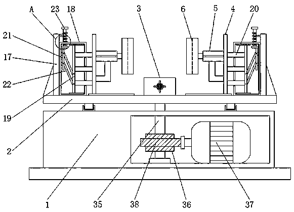
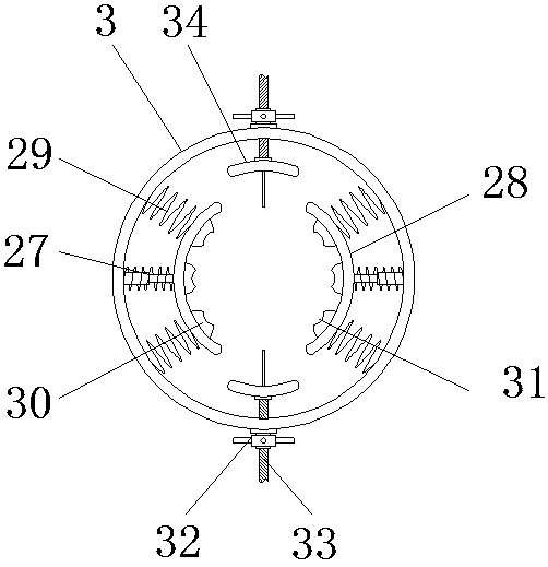
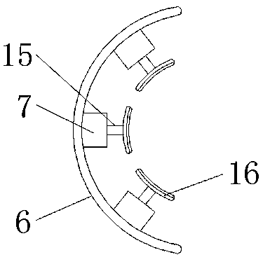
[0005] Aiming at the deficiencies of the prior art, the present invention provides a fixture based on the shaft chamfering process, which solves the problem that the shaft parts cannot be clamped well, and the clamping effect is very poor, and it cannot meet the requirements for different The problem of clamping shaft parts of large and small models

Method used


Image

  • A fixture for machining process based on shaft chamfering
  • A fixture for machining process based on shaft chamfering
  • A fixture for machining process based on shaft chamfering

Examples


Embodiment Construction

[0028] The following will clearly and completely describe the technical solutions in the embodiments of the present invention with reference to the accompanying drawings in the embodiments of the present invention. Obviously, the described embodiments are only some, not all, embodiments of the present invention. Based on the embodiments of the present invention, all other embodiments obtained by persons of ordinary skill in the art without making creative efforts belong to the protection scope of the present invention.

[0029] In describing the present invention, it is to be understood that the terms "opening", "upper", "lower", "thickness", "top", "middle", "length", "inner", "surrounding" etc. Indicating orientation or positional relationship is only for the convenience of describing the present invention and simplifying the description, and does not indicate or imply that the components or elements referred to must have a specific orientation, be constructed and operated in...


PUM


Abstract

The invention discloses a clamp for the shaft-type chamfering process, and relates to the technical field of shaft-type clamps. The clamp comprises a workbench; the top of the workbench is rotatably connected with a circular plate; the top of the circular plate is fixedly connected with a sleeve; sliding plates are slidably connected to the positions, on the two sides of the sleeve, of the top ofthe workbench correspondingly; one sides of the sliding plates are fixedly connected with hydraulic telescopic rods; and one ends of the hydraulic telescopic rods are fixedly connected with arc-shapedblocks. According to the clamp for the shaft-type chamfering process, shaft-type parts can be clamped well, the clamping effect is very good, the situation that the shaft-type parts move during chamfering, and consequently the chamfering quality and effect are affected is avoided, and clamping plates can be mounted and dismounted so as to be convenient to maintain; and the clamping plates with different sizes and types are convenient to mount to clamp the shaft-type parts with different sizes and types, and the comprehensiveness and usability of the shaft-type clamps are improved.

Description

technical field [0001] The invention relates to the technical field of shaft fixtures, in particular to a fixture based on a shaft chamfering process. Background technique [0002] In industrial products, shaft parts are suitable for one or more CNC machined part maintenance operations. Shaft parts are one of the typical parts often encountered in hardware accessories. They are mainly used to support transmission parts, transmit torque and bear loads. According to the different structural forms of shaft parts, they can generally be divided into optical shafts, stepped shafts and special-shaped shafts. There are three types of shafts; or divided into solid shafts, hollow shafts, etc., which are used in machines to support transmission parts such as gears and pulleys to transmit torque or motion. [0003] In real life, after the shaft parts are manufactured, they need to be chamfered. However, there are some shortcomings in the existing chamfering fixtures. For example, the e...

Claims


Application Information

Patent Timeline
Patent Type & Authority Patents(China)
IPC IPC(8): B23Q3/08B23Q1/26
CPCB23Q1/26B23Q3/082
Inventor 吴克桦吴雅楠郁伟玲
Owner GUANGZHOU ROVMA AUTO PARTS
Why Eureka
Try Eureka