
Thermal pressure-maintaining device

A pressure-holding device and pressure head technology, which is applied in the field of electronic product processing, can solve the problems of difficult weight control, easy-to-stick material of the pressure-holding head, and high production cost of rubber-covered parts, so as to achieve stable and reliable heat-holding pressure, and easy to avoid The effect of sticky material and precise positioning

Inactive Publication Date: 2020-11-03
苏州华智诚精工科技有限公司
View PDF7 Cites 2 Cited by
  • Summary
  • Abstract
  • Description
  • Claims
  • Application Information

AI Technical Summary

Problems solved by technology

However, the production cost of rubber-covered parts is relatively high, the anti-static effect is not good, and it has a certain degree of viscosity. The effect is difficult to guarantee

Method used


Image

  • Thermal pressure-maintaining device
  • Thermal pressure-maintaining device
  • Thermal pressure-maintaining device

Examples


Embodiment

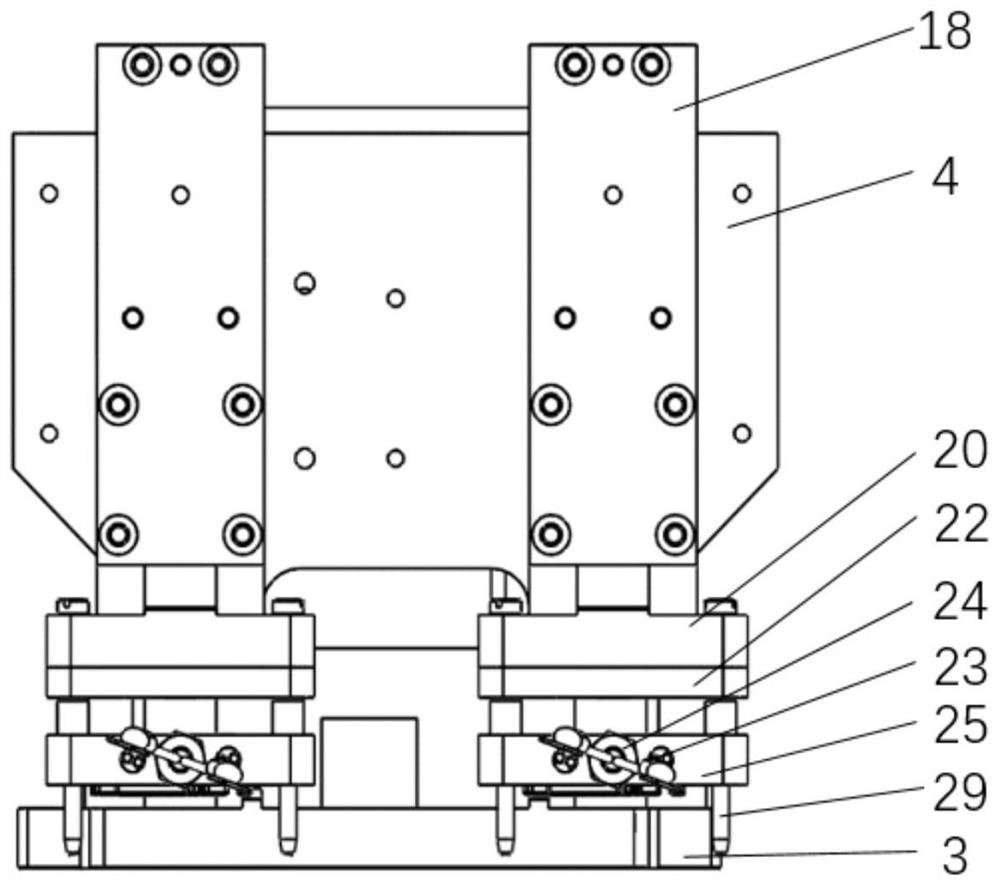
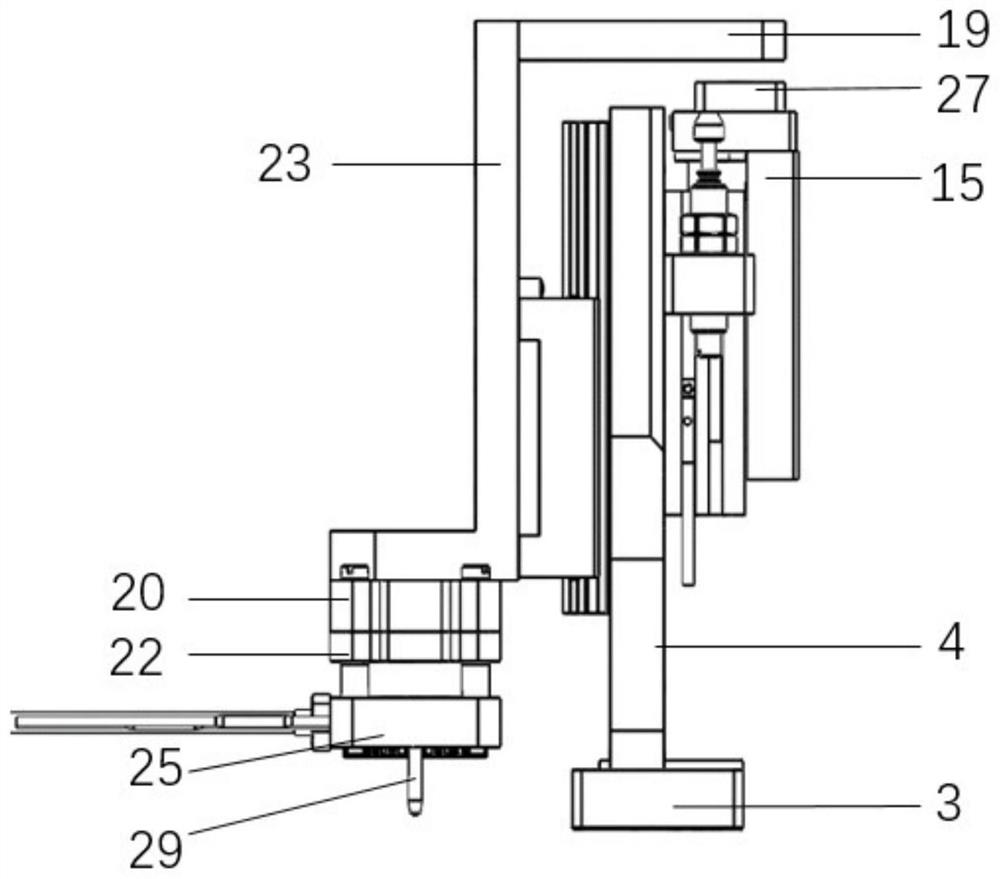
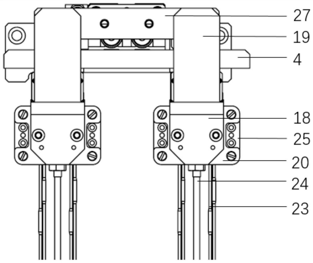
[0052] This embodiment provides a thermal pressure holding device, such as Figure 1~5 As shown, it includes: bottom plate 3, vertical plate 4, first slide cylinder 15, guide rail 9, slider 10, L plate 18, baffle plate 19, fixed block 20, heat insulation plate 22, heating rod 23, temperature controller Induction head 24, spring 25, pressure holding head 26, guide column 29;

[0053] Wherein, the vertical plate 4 is fixed on the base plate 3, the first slide table cylinder 15 is fixed on the back side of the vertical plate 4, the guide rail 9 is fixed on the front of the vertical plate 4, the L plate 18 is fixed on the slider 10, and the L plate 18 is connected with The fixed block 20, the fixed block 20, the heat shield 22, the spring 25, and the pressure-holding head 26 are connected into a whole through the connecting screw in turn from top to bottom. The induction head 24 is connected on the pressure-holding head 26 through its own thread and nut, and one end of the guide ...


PUM


Abstract

The invention relates to a thermal pressure-maintaining device, which comprises a bottom plate, a vertical plate, a first sliding table air cylinder, guide rails, sliding blocks, L-shaped plates, heating rods, pressure-maintaining heads, guiding columns and the like. The thermal pressure-maintaining device provided by the invention is good in bonding performance and high in yield, and the defectsthat a traditional pressure-maintaining structure adopts a rubber-coated pressure-maintaining head, which is high in cost and poor in anti-static effect, the pressure-maintaining head is prone to sticking materials after pressure maintaining, the risk of sticking the materials up exists, and the pressure-maintaining effect is difficult to ensure are overcome.

Description

technical field [0001] The application belongs to the technical field of electronic product processing, and in particular relates to a thermal pressure maintaining device for automatic assembly and film application of SIP boards of electronic communication equipment such as mobile phones and watches. Background technique [0002] The SIP boards of electronic communication equipment such as mobile phones and watches need to apply a heat-holding device when the film is automatically assembled. The self-weight of the code reaches the pressure-holding effect. For example, CN209289752U discloses a 3D glass protective film coating equipment that adopts a rubberized roller method to pre-attach the protective film to the 3D curved glass. However, the production cost of rubber-covered parts is relatively high, the anti-static effect is not good, and it has a certain degree of viscosity. The effect is difficult to guarantee. [0003] Patent CN108973143A discloses a heating and press...

Claims


Application Information

Patent Timeline
Patent Type & Authority Applications(China)
IPC IPC(8): B29C63/02
CPCB29C63/0004B29C63/02
Inventor 朱明园何庆
Owner 苏州华智诚精工科技有限公司
Learn More