
Drive control structure of mobile medical equipment

A mobile medical and drive control technology, applied in surgical equipment, motor vehicles, medical science, etc., can solve problems such as single function, no power assist system, no lifting components, etc., to increase the contact area, enhance stability, and good applicability Effect

Inactive Publication Date: 2020-11-03
董浩
View PDF10 Cites 3 Cited by
  • Summary
  • Abstract
  • Description
  • Claims
  • Application Information

AI Technical Summary

Problems solved by technology

[0003] In hospitals, some expensive or bulky medical equipment cannot be configured and installed for each bed, such as ventilators, mobile CT equipment, etc.
When patients need to use these devices, the medical staff use carts to transport the devices to the hospital bed or the operating room. The existing carts have a simple structure, a single function, no power assist system, no lifting components, and are suitable for transporting heavy equipment. Time-consuming and labor-intensive; due to the difference in the height of the hospital bed, there are also cases where the equipment needs to be manually adjusted after the equipment is delivered, which takes up the rescue time

Method used


Image

  • Drive control structure of mobile medical equipment
  • Drive control structure of mobile medical equipment
  • Drive control structure of mobile medical equipment

Examples


Embodiment Construction

[0025] The following will clearly and completely describe the technical solutions in the embodiments of the present invention with reference to the accompanying drawings in the embodiments of the present invention. Obviously, the described embodiments are only some, not all, embodiments of the present invention. Based on the embodiments of the present invention, all other embodiments obtained by persons of ordinary skill in the art without making creative efforts belong to the protection scope of the present invention.

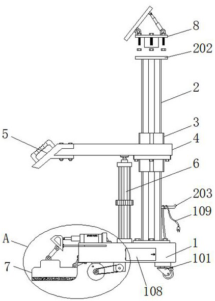
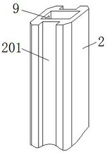
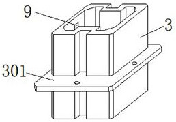
[0026] Such as Figure 1-8 As shown, the present invention provides a technical solution: a drive control structure for mobile medical equipment, including a base 1, a limiting channel steel 2 and a brake mechanism 7 installed on the base 1, and a stopper channel steel 2 mounted on the top Auxiliary storage mechanism 8, sleeve pipe 3 movably connected with limit channel steel 2, storage board 4 connected with sleeve pipe 3, control panel 5 fixed on one side of...


PUM


Abstract

The invention discloses a drive control structure of mobile medical equipment, and relates to the technical field of driving mechanisms. The structure comprises a base, limiting channel steel, a brakemechanism, an auxiliary storage mechanism, a sleeve, a storage plate and a control plate, wherein the limiting channel steel and the brake mechanism are mounted on the base, the auxiliary storage mechanism is mounted at the top of the limiting channel steel, the sleeve is movably connected with the limiting channel steel, the storage plate is connected with the sleeve, and the control plate is fixed to one side of the storage plate; the bottom of the storage plate is connected with a lifting cylinder; the bottom of the lifting cylinder is fixed to the top of the base, two steering wheels arefixed to one side of the bottom of the base close to two ends, and a power wheel set is fixed to the other side of the bottom of the base. A device can be pushed in a power-assisted mode in the movingprocess, the physical strength of medical staff is saved, the contact area between a brake pad and the ground is effectively increased through the structure of the brake mechanism, then the stabilityof the device after braking is enhanced, a storage battery is arranged in the device, and therefore the device has good applicability when emergency treatment is conducted along with an ambulance.

Description

technical field [0001] The invention relates to the technical field of drive mechanisms, in particular to a drive control structure for mobile medical equipment. Background technique [0002] Medical equipment is the most basic element of medical treatment, scientific research, teaching, institutions, and clinical disciplines, including professional medical equipment and household medical equipment. Medical equipment is the basic condition for continuously improving the level of medical science and technology, and it is also an important symbol of modernization. Medical equipment has become an important field of modern medicine. The development of medical treatment depends to a large extent on the development of instruments, and even in the development of the medical industry, its breakthrough of bottlenecks also plays a decisive role. [0003] In hospitals, some expensive or bulky medical equipment cannot be configured and installed for each bed, such as ventilators, mobil...

Claims


Application Information

Patent Timeline
IPC IPC(8): B62B5/00B62B5/04B62B3/02A61B50/13
CPCA61B50/13B62B3/02B62B5/0036B62B5/0053B62B5/0066B62B5/0457
Inventor 关莉
Owner 董浩
Learn More