Efficient food fermentation equipment

A food fermentation and equipment technology, applied in the field of high-efficiency food fermentation equipment, can solve problems such as low alcohol content of wort, influence on beer production, and reduction of malt content

Pending Publication Date: 2020-11-03
北京琪天科技有限公司
View PDF0 Cites 2 Cited by
  • Summary
  • Abstract
  • Description
  • Claims
  • Application Information

AI Technical Summary

Problems solved by technology

[0002] The production process of beer is prepared through many processes, among which the fermentation of wort is an important process. Before fermentation, hops and sugar are added to the wort to fully mix, and then put into the fermentation tank to add microorganisms for fermentation; existing In the process of fermenting wort by using fermenter in the technology, since hops contain pectin, pectin dissolves in water to form a viscous colloidal solution. Add wort to the fermenter, and part of the malt in the wort is covered by the colloidal solution. Sticking to the inner wall of the tank, resulting in a reduction in the malt content at the bottom of the tank, resulting in low alcohol content in the fermented wort, which affects beer production

Method used


Image

  • Efficient food fermentation equipment
  • Efficient food fermentation equipment
  • Efficient food fermentation equipment

Examples


Embodiment 1

[0025] as attached figure 1 To attach Figure 5 Shown:

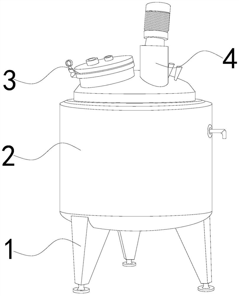
[0026] The invention provides a high-efficiency food fermentation equipment, the structure of which includes a bracket 1, a tank body 2, a top cover 3, and a motor 4, the bracket 1 is welded to the bottom of the tank body 2, and the top cover 3 is movable with the top of the tank body 2 Together, the motor 4 is installed on the top cover 3 top.

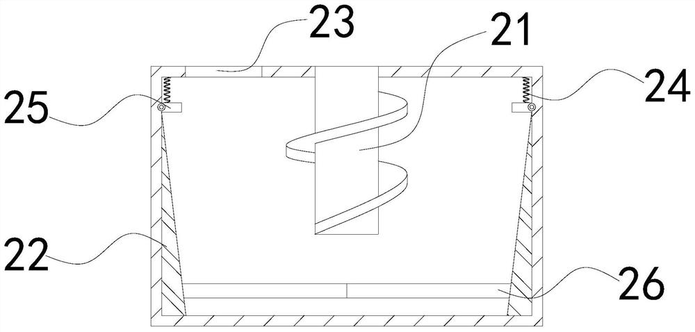
[0027] The tank body 2 is provided with a stirring rod 21, a block 22, an air outlet 23, a spring 24, a support block 25, and a moving ring 26. The stirring rod 21 runs through the center of the top of the tank body 2, and the block 22 is fixed on On both sides of the inner wall of the tank body 2, the air outlet 23 runs through the top center of the tank body 2 to the left, the support block 25 is installed on the inner top of the tank body 2, and the spring 24 is connected between the top of the support block 25 and the inside of the tank body 2 Between the tops, the moving...

Embodiment 2

[0034] as attached Figure 6 to attach Figure 7 Shown:

[0035] Wherein, the slider d5 is provided with a top block r1, a card board r2, a slide rail r3, a bottom bar r4, a moving block r5, and a steel block r6, and the top block r1 is nested on the inner top of the slider d5, and the card The plate r2 is set inside the slider d5, and the top is movably matched with the top block r1, the slide rail r3 is set inside the clamping plate r2, the bottom rod r4 is movably matched with the slide rail r3 through the moving block r5, and the steel block r6 is located at the inner bottom of the slider d5 and is located on both sides of the bottom bar r4. The bottom bar r4 is in the shape of an inverted trapezoid, and the straight drop of the trapezoid gradually decreases from top to bottom, which is beneficial to reduce the gap between the bottom bar r4 and the groove d3. Increase the contact area, increase the pressure, and speed up the liquid removal from the surface of the groove ...


PUM


Abstract

The invention discloses efficient food fermentation equipment. The efficient food fermentation equipment structurally comprises a bracket, a tank body, a top cover and a motor, wherein the bracket iswelded at the bottom of the tank body, the top cover is movably clamped with the top of the tank body, and the motor is mounted at the top of the top cover. When wort is added into a fermentation tank, part of malt in the wort is stuck on the inner wall of the tank body by a colloidal solution; a moving ring in the tank body rises along with the increase of the wort, a push block pushes the malt in the tank body upwards to fall to the bottom of the tank body, and the situation that part of malt in the wort is stuck to the inner wall of the tank body by the colloidal solution, so that the maltcontent at the bottom of the tank body is reduced, the alcoholic strength in the fermented wort is low, and beer production is affected is reduced. As the surface of the malt contains the colloidal solution, and the colloidal solution is viscous, part of the malt is accumulated on the surfaces of grooves, the gliding speed of the malt is reduced, the malt on the surfaces of the grooves is removedthrough hairbrushes at the bottom of a sliding block, the malt accumulated on the surfaces of the grooves is reduced, and the removed malt is accelerated to slide down along the grooves.

Description

technical field [0001] The invention belongs to the field of food fermentation, and more specifically, relates to a high-efficiency food fermentation equipment. Background technique [0002] The production process of beer is prepared through many processes, among which the fermentation of wort is an important process. Before fermentation, hops and sugar are added to the wort to fully mix, and then put into the fermentation tank to add microorganisms for fermentation; existing In the process of fermenting wort by using fermenter in the technology, since hops contain pectin, pectin dissolves in water to form a viscous colloidal solution. Add wort to the fermenter, and part of the malt in the wort is covered by the colloidal solution. Sticking to the inner wall of the tank, the malt content at the bottom of the tank is reduced, and the alcohol content in the fermented wort is low, which affects beer production. Contents of the invention [0003] In order to solve the above-m...

Claims


Application Information

Patent Timeline
Patent Type & Authority Applications(China)
IPC IPC(8): C12C11/00B08B9/087
CPCB08B9/087C12C11/006
Inventor 曾振崇
Owner 北京琪天科技有限公司
Why Eureka
Try Eureka