
Energy-saving annealing furnace

An annealing furnace, energy-saving technology, used in furnaces, furnace types, heat treatment furnaces, etc., can solve problems such as unfavorable placement of racks, reduced charging space, hidden safety hazards, etc., to avoid uneven heating and high temperature. Uniformity, the effect of eliminating safety hazards

Active Publication Date: 2022-04-05
NINGBO SACHSEN IND TECH CO LTD
View PDF0 Cites 0 Cited by
  • Summary
  • Abstract
  • Description
  • Claims
  • Application Information

AI Technical Summary

Problems solved by technology

[0005] 1. Due to the integrated structure, the overall weight of the pallet after the material rack is loaded is large, and the pallet must be transported by a three-dimensional material truck. The three-dimensional material truck must first lift the pallet through the hydraulic system and move it to the annealing furnace Or after the column of the preparation table corresponds to the position, the hydraulic system of the material truck is lowered, so that the integrated tray can be located on the column, so a certain height must be reserved above the annealing furnace and below the column for the lifting of the pallet and the material vehicle Avoid the position, which reduces the effective charging space of the annealing furnace by about 6 cubic meters (length 6 meters * width 2 meters * height 0.5), which greatly reduces the production capacity of the annealing furnace;
[0006] 2. The overall size is relatively large (about 6 meters in length, about 2 meters in width, and about 0.3 meters in height). Since there are many aluminum coils loaded on the tray during annealing, weighing more than 20 tons, it is easy to cause heat after long-term high-temperature heating. Deformation, especially when the pallet will collide with the column in the vertical direction during the descent process, the contact part between the pallet and the column is often sunken and arched upward, resulting in overall distortion and deformation, which is not conducive to the stable placement of the rack;
[0007] 3. The contact surface between the deformed tray and the column is not smooth. When it is in place, it is easy to cause the tray to slide and shift under the action of gravity, which causes the overall lateral movement of the loaded material frame. In severe cases, it will cause the material frame to tilt, Serious production accidents such as pallet overturning and aluminum coil bumping
Although the air guide tube can send hot air into the lower part of the annealing furnace, it has the following disadvantages: 1. The air outlet position is concentrated, which easily leads to uneven heating of the aluminum alloy coil at the bottom; Alloy coils are easy to be torn, and a large number of aluminum alloy fragments are carried to various parts of the furnace by hot air, and even enter the circulating fan, causing fan failure and posing a huge safety hazard; 3. High defective rate

Method used


Image

  • Energy-saving annealing furnace
  • Energy-saving annealing furnace
  • Energy-saving annealing furnace

Examples


Embodiment 1

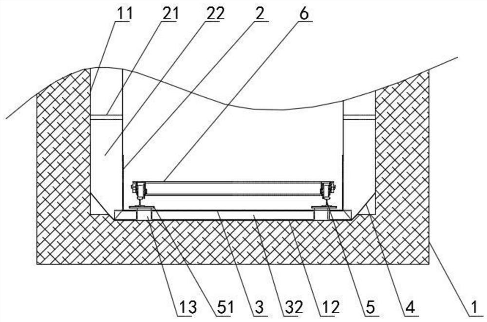
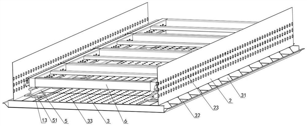
[0057] as attached figure 1 , 2 , 3, the energy-saving annealing furnace of this embodiment includes a furnace body 1, a vertical guide plate 2, a bottom air outlet hole plate 3, a guide plate 4, a track 5, a horizontal tray 6, a connecting mechanism 7 and a roller mechanism 8.

[0058] The vertical deflector 2 in the furnace body 1 is fixedly connected with the side wall cotton pressing plate 11 through the connecting rod 21, and a vertical air duct 22 with a width of 200mm is formed between the vertical deflector 2 and the side wall cotton pressing plate 11. The bottom air outlet hole plate 3 is fixedly connected with the furnace bottom cotton pressing plate 12 through a C-shaped connection partition plate 31, and a 50 mm high bottom air duct 32 is formed between the bottom air outlet hole plate 3 and the furnace bottom cotton pressing plate 12, and C The bottom air passage 32 is separated by the C-shaped connection partition plate 31 , so that an independent chamber-type a...

Embodiment 2

[0069] The energy-saving annealing furnace of this embodiment includes a furnace body 1, a vertical deflector plate 2, a bottom air outlet hole plate 3, a guide plate 4, a track 5, a horizontal tray 6, a connecting mechanism 7 and a roller mechanism 8.

[0070] The position of each part is basically the same as that of Embodiment 1, the difference is:

[0071] (1) The width of the vertical air duct 22 is 400 mm, and the height of the bottom air duct 32 is 200 mm.

[0072] (2) As attached Figure 7 As shown, the rail 5 is fixed on the installation platform 51 through the rail pressure plate 52 , and the installation platform 51 is welded and fixed on the bottom column 13 .

[0073] (3) If attached Figure 8 As shown, the three horizontal trays 6 are connected horizontally through the connection mechanism 7 to form a whole, and the horizontal trays 6 at the furnace mouth end and the furnace inner end are respectively fixed with push-pull parts 67 . The horizontal pallet 6 is ...


PUM

PropertyMeasurementUnit
thermal resistanceaaaaaaaaaa

Abstract

The invention relates to the field of annealing furnace production, and specifically provides an energy-saving annealing furnace. The annealing furnace includes a furnace body, and a vertical air duct is formed between the vertical deflector in the furnace body and the side wall cotton pressing plate of the furnace body. It is characterized in that the furnace body is provided with a bottom air outlet hole plate and at least two horizontal trays. The bottom air channel is formed between the air outlet hole plate and the furnace bottom cotton pressing plate, and the bottom air channel is connected with the vertical air channel. The horizontal tray is set on the bottom air outlet hole plate through the roller mechanism, and two adjacent horizontal trays are connected through connection mechanism activities. Compared with the prior art, the energy-saving annealing furnace of the present invention can effectively increase the charging capacity of the annealing furnace, reduce tray deformation, and reduce production safety risks, and has good popularization and application value.

Description

technical field [0001] The invention relates to the field of annealing furnace production, and specifically provides a high-efficiency and energy-saving annealing furnace. Background technique [0002] In the finished product stage, most of the aluminum alloy coils need to undergo high-temperature heat treatment (200°C-520°C) for a certain period of time (20-300h) in the aluminum annealing furnace according to the quality control requirements, so as to eliminate the processing stress of the aluminum material, improve the mechanical properties of the structure, Process goals such as improving surface cleanliness. [0003] On the one hand, in order to maximize the output of the annealing furnace, multiple aluminum alloy coils are often suspended in one material frame during annealing production, and multiple material frames are loaded on an integrated pallet, and the pallet loaded with material frames is pushed, Transport it to the annealing furnace and place it on the column...

Claims


Application Information

Patent Timeline
Patent Type & Authority Patents(China)
IPC IPC(8): C21D9/54C21D1/26C22F1/04
CPCC21D9/54C21D9/0056C21D1/26C22F1/04
Inventor 郑旺林刘玖鑫符淋江
Owner NINGBO SACHSEN IND TECH CO LTD
Learn More