Coating machine

A coating machine and coating technology, applied in coating, metal material coating process, ion implantation plating, etc., can solve the problem of uneven coating thickness and achieve the effect of improving coating yield

Pending Publication Date: 2020-11-03
GUANGDONG UCAN ROBOT TECH CO LTD
View PDF0 Cites 0 Cited by
  • Summary
  • Abstract
  • Description
  • Claims
  • Application Information

AI Technical Summary

Problems solved by technology

[0002] In the process of workpiece processing, it is often necessary to coat the workpiece to improve the performance of the workpiece. In actual load manufacturing, the cutting tool is one of the basic accessories commonly used in various processing equipment. For example, electronic products need to use built-in circuits. Drilling pins are one of the commonly used tools for drilling holes on built-in circuit boards. In order to prolong the service life of tools such as drill pins, it is often necessary to coat the outside of the tool. Standing still during the process, it is easy to cause uneven coating thickness and poor

Method used


Image

  • Coating machine
  • Coating machine
  • Coating machine

Examples


Embodiment Construction

[0035] In order to facilitate the understanding of those skilled in the art, the present invention will be further described below in conjunction with the embodiments and accompanying drawings, and the contents mentioned in the implementation modes are not intended to limit the present invention.

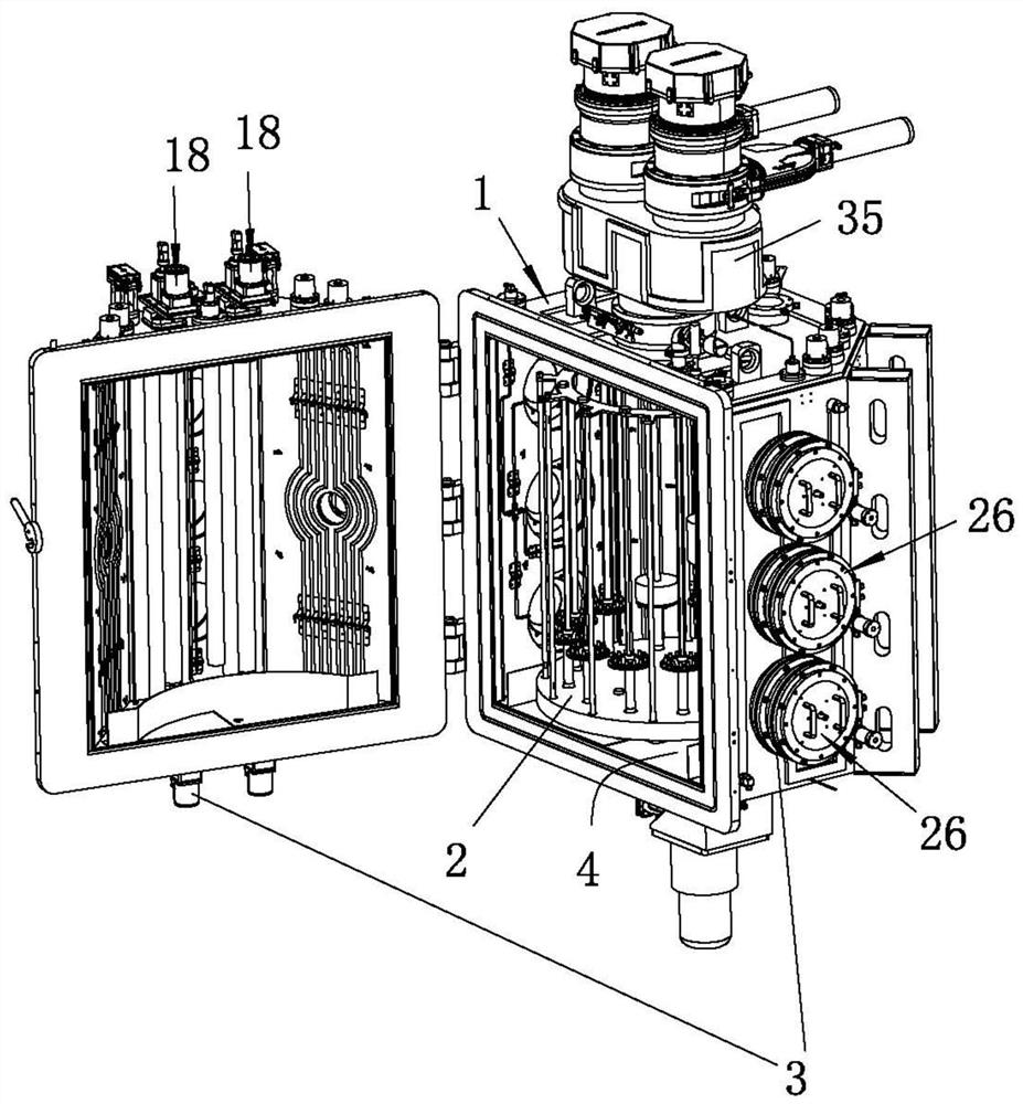
[0036] see Figure 1 to Figure 8 As shown, a coating machine of the present invention includes a chassis 1, a loading mechanism 2 and a coating mechanism 3 installed on the chassis 1. In this embodiment, the chassis 1 is formed by connecting a plurality of metal plates. 1 has an accommodating cavity 4, the loading mechanism 2 is located in the accommodating cavity 4 of the chassis 1 and is used to carry workpieces to be coated (such as knives, etc.), and the coating mechanism 3 is used to supply coating materials so that the coating materials are coated A protective coating is formed on the workpiece carried by the loading mechanism 2 .

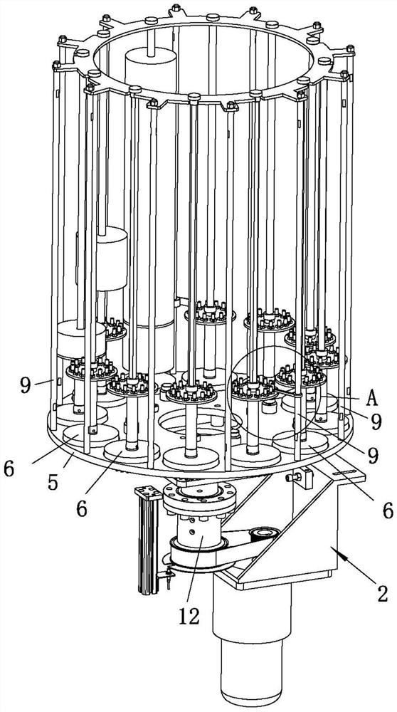
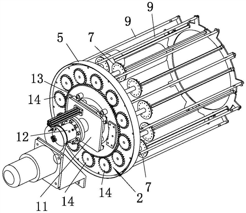
[0037] The loading mechanism 2 includes a f...


PUM


Abstract

The invention relates to the technical field of workpiece coating, and particularly discloses a coating machine which comprises a case, a material carrying mechanism and a coating mechanism, wherein the material carrying mechanism and the coating mechanism are arranged in the case, the material carrying mechanism is used for carrying a workpiece to be coated, and the coating mechanism coats the workpiece carried by the material carrying mechanism with a coating material; the material carrying mechanism comprises a first frame body, a carrying frame rotationally arranged on the first frame body, a first driving piece used for driving the carrying frame to rotate, a first carrier rotationally arranged on the carrying frame and used for carrying the workpiece, a contact wheel arranged on thefirst carrier and a matching piece arranged on the carrying frame and used for being in contact fit with the contact wheel so as to enable the first carrier to rotate; the coating material supplied bythe coating mechanism is coated on the workpiece carried by the first carrier; and in the workpiece coating process, the first driving piece drives the carrying frame to enable the workpiece carriedby the first carrier to revolve, the first carrier drives the workpiece to rotate by means of abutting fit of the matching piece and the contact wheel, and then the coating yield of the workpiece is increased.

Description

technical field [0001] The invention relates to the technical field of workpiece coating, and in particular discloses a coating machine. Background technique [0002] In the process of workpiece processing, it is often necessary to coat the workpiece to improve the performance of the workpiece. In actual load manufacturing, the cutting tool is one of the basic accessories commonly used in various processing equipment. For example, electronic products need to use built-in circuits. Drilling pins are one of the commonly used tools for drilling holes on built-in circuit boards. In order to prolong the service life of tools such as drill pins, it is often necessary to coat the outside of the tool. Stand still during the process, it is easy to cause uneven coating thickness and poor quality. Contents of the invention [0003] In order to overcome the disadvantages and deficiencies in the prior art, the purpose of the present invention is to provide a coating machine, the first...

Claims


Application Information

Patent Timeline
IPC IPC(8): C23C14/50C23C14/24
CPCC23C14/24C23C14/505
Inventor 王俊锋王锋袁明李浩
Owner GUANGDONG UCAN ROBOT TECH CO LTD
Why Eureka
Try Eureka