Rail transit elevated sound barrier

A technology for rail transit and overhead sound, which is applied in lighting and heating equipment, construction, cleaning methods, etc., and can solve problems such as dust removal and inability to ventilate through sound barriers

Inactive Publication Date: 2020-11-03
邢玉祥
View PDF0 Cites 3 Cited by
  • Summary
  • Abstract
  • Description
  • Claims
  • Application Information

AI Technical Summary

Problems solved by technology

However, the existing sound barriers only have a simple noise reduction function, but cannot ventilate and remove dust in the sound barrier.

Method used


Image

  • Rail transit elevated sound barrier
  • Rail transit elevated sound barrier
  • Rail transit elevated sound barrier

Examples


specific Embodiment approach 1

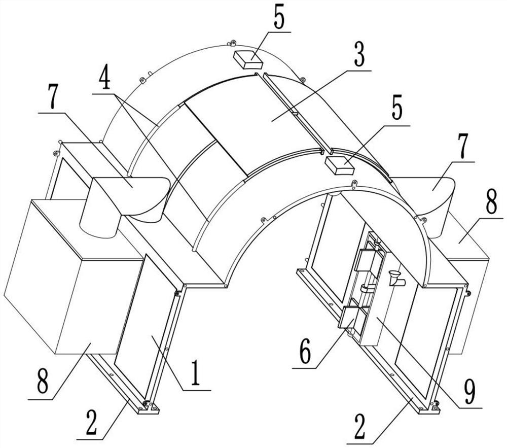
[0033] Combine below Figure 1-11 Describe this embodiment, the present invention relates to the technical field of sound barriers, more specifically, an elevated sound barrier for rail transit, including an elevated sound barrier component 1, a fixed connection base device 2, a curved surface recovery ventilation device 3, and a recovery telescopic connection device 4 , solar lighting device 5, rotating dust absorbing device 6, dust transfer pipe member 7, dust absorbing storage device 8 and shielding frame body 9, can connect a plurality of this devices together and be fixed on the both sides of track, allow a plurality of fixed The posts 1-7 are respectively slidably connected in a plurality of fixed sockets 1-6 adjacent thereto, and then a plurality of adjacent connecting seats 1-5 are used to fix two adjacent devices together to form a long Sound barrier, and the air in the long sound barrier may not be very good, so you can move two shielding curved plates 3-2 to expose th...

specific Embodiment approach 2

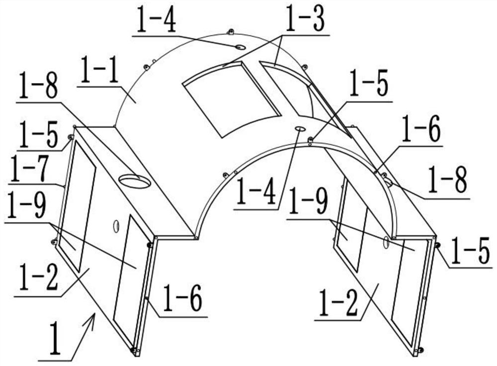
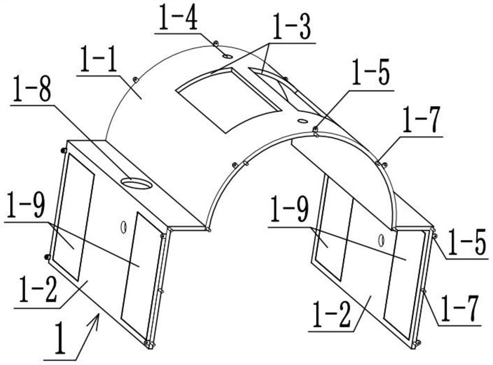
[0036] Combine below Figure 1-11 Describe this embodiment, this embodiment will further explain Embodiment 1. The elevated sound barrier component 1 includes a semi-arched plate 1-1, a vertical sound barrier plate 1-2, a ventilation port 1-3, and a lighting hole 1-4 , connecting seat 1-5, fixed socket 1-6, fixed post 1-7, dust suction hole 1-8 and light-transmitting window 1-9, and the semi-arched plate 1-1 plays the role of shielding and noise reduction, Both sides below the semi-arched plate 1-1 are fixedly connected with a vertical sound barrier plate 1-2, and the vertical sound barrier plate 1-2 plays the role of bearing connection and can also reduce noise. The semi-arched plate 1 Both ends above -1 are provided with air vents 1-3, after the air vents 1-3 are provided, the air in the device can be ventilated to ensure that the device will not be stuffy. There are two lighting holes 1-4, and the two lighting holes 1-4 can provide space for the fixed lamp holder 5-2 to pa...

specific Embodiment approach 3

[0038] Combine below Figure 1-11 Describe this embodiment, this embodiment will further explain the second embodiment, the fixed connection base device 2 includes the anchor plate 2-1 and the anchor hole 2-2, the anchor plate 2-1 plays the role of load-bearing connection, A plurality of anchor holes 2-2 are arranged on the anchor plate 2-1, so that a plurality of fixing bolts respectively pass through a plurality of anchor holes 2-2 and are connected under the ground, so that the device can be fixed on the ground, There are two fixedly connected base devices 2, and the two anchor plates 2-1 are respectively fixedly connected under the two vertical sound barrier plates 1-2.


PUM


Abstract

The invention relates to the technical field of sound barriers, in particular to a rail transit elevated sound barrier. The sound barrier comprises an elevated sound barrier component, a fixed connection base device, a curved surface recovery ventilation device, a recovery telescopic connection device, a solar lighting device, a rotary dust absorption device, a dust transfer pipeline component, adust adsorption storage device and a shielding frame body. A plurality of devices can be connected together and fixed on two sides of a rail, a plurality of fixed inserting columns are respectively connected into a plurality of adjacent fixed inserting holes in a sliding manner, two adjacent devices are fixed together by utilizing a plurality of adjacent connecting seats, and two shielding bent plates are moved to expose two air vents; when a train passes through the long sound barrier, a rapid wind speed can be generated, so the plurality of absorption fan blades can be driven to rotate, dustin the long sound barrier can be absorbed into the absorption box and water can be absorbed, and a dust removal effect is achieved.

Description

technical field [0001] The invention relates to the technical field of sound barriers, in particular to a rail transit elevated sound barrier. Background technique [0002] Sound barriers are mainly used for sound insulation and noise reduction of roads, expressways, elevated composite roads and other noise sources. It is divided into reflective sound barriers for pure sound insulation, and composite sound barriers that combine sound absorption and sound insulation. The latter is a more effective sound insulation method. It refers to the wall structure set up beside the railway and road to reduce the impact of driving noise on nearby residents. A soundproof wall is also called a sound barrier. A facility is inserted between the sound source and the receiver, so that the sound wave propagation has a significant additional attenuation, thereby reducing the impact of noise in a certain area where the receiver is located. Such a facility is called a sound barrier. Divided int...

Claims


Application Information

Patent Timeline
IPC IPC(8): E01F8/00E01H1/08F21S9/03F21V33/00
CPCE01F8/00E01H1/0836F21S9/03F21V33/00
Inventor 邢玉祥
Owner 邢玉祥
Why Eureka
Try Eureka