Steel structure scaffold

A technology for scaffolding and steel structures, applied in the field of steel structure scaffolding, can solve problems such as troublesome, time-consuming manpower, inability to adjust length and width, etc.

Pending Publication Date: 2020-11-03
岳伟久
View PDF5 Cites 8 Cited by
  • Summary
  • Abstract
  • Description
  • Claims
  • Application Information

AI Technical Summary

Problems solved by technology

[0002] During building construction, scaffolding will be erected on the outer wall of the building. The structure of the scaffolding is relatively simple. It is generally assembled by scaffolding rods, connectors and screws. Therefore, the scaffolding needs to be disassembled by screws, which is very troublesome. After the screws are locked and assembled , the screws often loosen, resulting in the overall loosening of the scaffolding, which is very dangerous
Furthermore, the length and width of the entire scaffold structure are fixed, and the length and width cannot be adjusted at any time according to the needs. If the length and width of the entire scaffold need to be changed, the entire scaffold needs to be disassembled and then a suitable scaffold should be selected. It takes a long time and manpower to assemble the scaffold with the required length and width.

Method used


Image

  • Steel structure scaffold
  • Steel structure scaffold
  • Steel structure scaffold

Examples


specific Embodiment approach 1

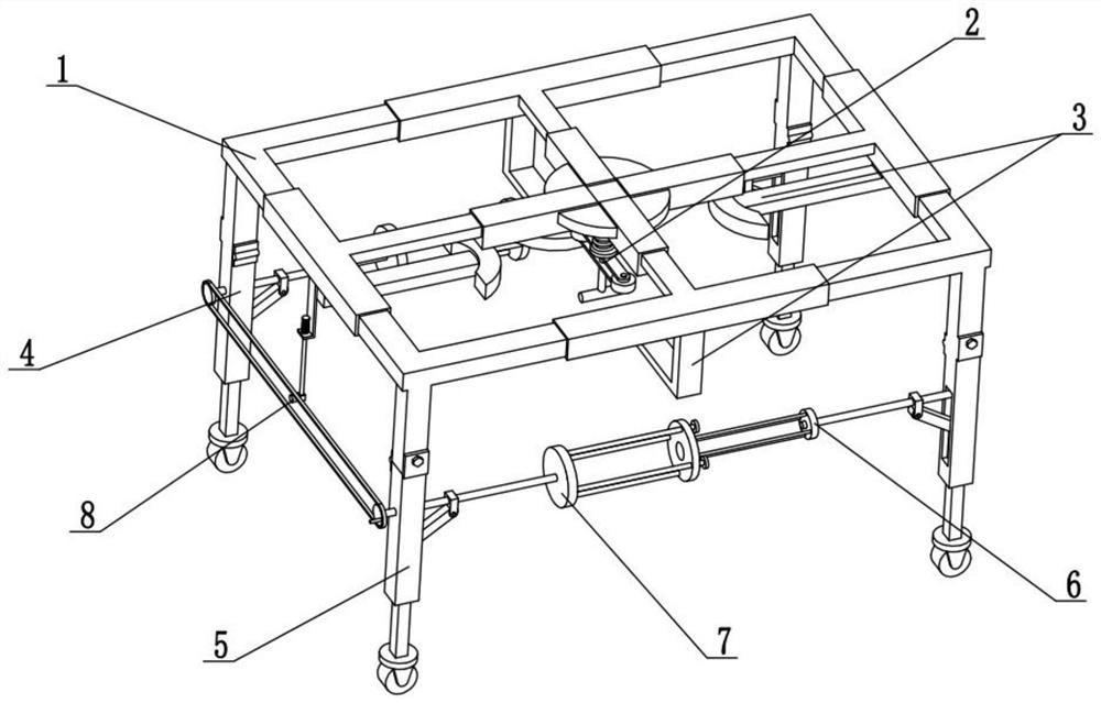
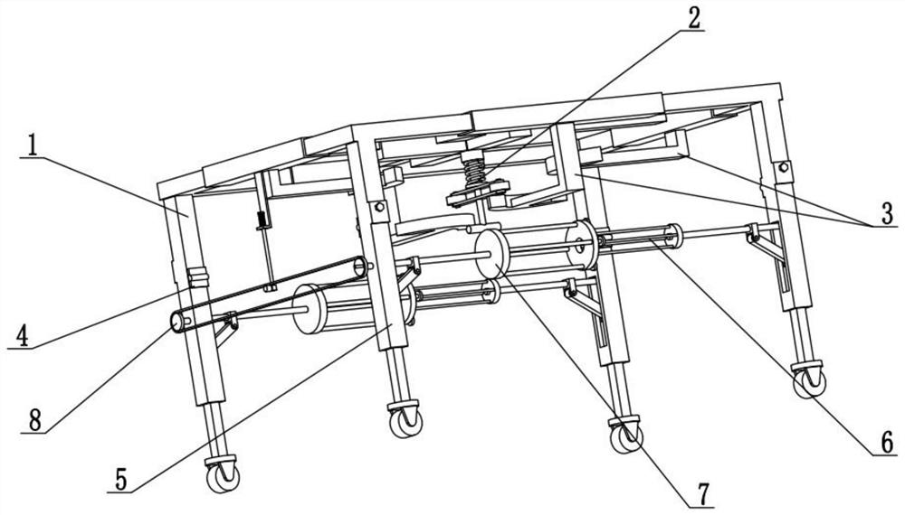
[0029] Combine below Figure 1-10 Describe this embodiment, the present invention relates to the technical field of construction, more specifically a steel scaffolding, including a telescopic frame 1 on the top surface, an extension and rotation mechanism 2, a suspension matching push rod 3, adjustable short legs 4, adjustable Long leg 5, follow-up rotating arm 6, adjustable active beam 7 and lifting linkage mechanism 8, the adjustable short leg 4 and the adjustable long leg 5 are all provided with two, two adjustable short legs 4 are respectively hinged to the left and right ends of the rear end of the top telescopic frame 1, and the two adjustable long legs 5 are respectively hinged to the left and right ends of the front end of the top telescopic frame 1, and the extension rotation mechanism 2 is fixedly connected to the bottom of the top telescopic frame 1 end, there are four suspension matching push rods 3, and the four suspension matching push rods 3 are all fixedly conn...

specific Embodiment approach 2

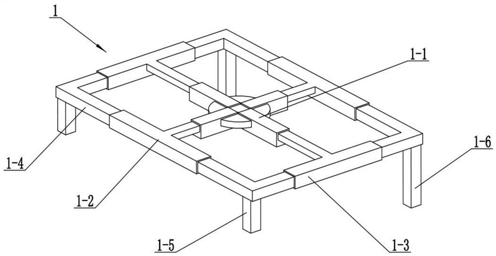
[0032] Combine below Figure 1-10 Describe this embodiment, this embodiment will further explain the first embodiment, the top telescopic frame 1 includes a cross slide 1-1, a front and rear moving sleeve 1-2, a left and right moving sleeve 1-3, and a right-angle sliding beam 1-4, short connecting legs 1-5 and long connecting legs 1-6, two front and rear moving sleeves 1-2 are respectively slidably connected to the front and rear ends of the cross slideway 1-1, two left and right moving sleeves 1- 3 are respectively slidably connected to the left and right ends of the cross slideway 1-1, and the two ends of the four right-angled sliding beams 1-4 are respectively slidably connected to two left and right moving sleeves 1-3 and two front and rear moving sleeves 1-2 Inside, the two short connecting legs 1-5 are respectively fixedly connected to the bottom ends of the two right-angle sliding beams 1-4 at the front end, and the two long connecting legs 1-6 are respectively fixedly ...

specific Embodiment approach 3

[0035] Combine below Figure 1-10 Describe this embodiment, this embodiment will further explain the second embodiment, the extension and rotation mechanism 2 includes a hollow cylinder 2-1, a sliding pole 2-2, a tension spring 2-3, a horizontal beam 2-4, Pushing auxiliary wheels 2-5 and rotating handle 2-6, rotating handle 2-6 is fixedly connected to the bottom of horizontal beam 2-4, pushing auxiliary wheels 2-5 is provided with two, two pushing auxiliary wheels 2- 5 respectively rotate and connect to the front and rear ends of the horizontal beam 2-4, the sliding vertical rod 2-2 is fixedly connected to the horizontal beam 2-4, the sliding vertical rod 2-2 is slidingly connected in the hollow cylinder 2-1, and the hollow circle The cylinder 2-1 is fixedly connected to the bottom of the cross slideway 1-1, and a tension spring 2-3 is fixedly connected between the hollow cylinder 2-1 and the horizontal beam 2-4.


PUM


Abstract

The invention relates to the technical field of buildings, in particular to a steel structure scaffold which can be adjusted in length and width at any time according to needs. The steel structure scaffold comprises a top surface telescopic framework, an extension rotating mechanism, suspension matching push rods, adjustable short support legs, adjustable long support legs, follow-up rotating arms, adjusting driving cross beams and a lifting linkage mechanism; a constructor drives the four suspension matching push rods to move by rotating the extension rotating mechanism, and the four suspension matching push rods drive the top surface telescopic framework to adjust the width and the length of the top surface telescopic framework, so that the area of the top surface telescopic framework ischanged; and meanwhile, the lifting linkage mechanism can be used for driving the two adjusting driving cross beams and the two follow-up rotating arms to rotate, the two adjustable short support legs and the two adjustable long support legs are driven by the two adjustable driving cross beams and the two follow-up rotating arms to be adjusted in height, the conditions that the whole scaffold isdisassembled and then appropriate scaffold rods are selected for assembly are not needed, and time and labor are saved.

Description

technical field [0001] The invention relates to the technical field of construction, in particular to a steel scaffolding. Background technique [0002] During building construction, scaffolding will be erected on the outer wall of the building. The structure of the scaffolding is relatively simple. It is generally assembled by scaffolding rods, connectors and screws. Therefore, the scaffolding needs to be disassembled by screws, which is very troublesome. After the screws are locked and assembled , Often there will be loose screws, which will lead to the overall loosening of the scaffolding, which is very dangerous. Furthermore, the length and width of the entire scaffold structure are fixed, and the length and width cannot be adjusted at any time according to the needs. If the length and width of the entire scaffold need to be changed, the entire scaffold needs to be disassembled and then a suitable scaffold should be selected. It takes a long time and manpower to assembl...

Claims


Application Information

Patent Timeline
Patent Type & Authority Applications(China)
IPC IPC(8): E04G1/24E04G1/18
CPCE04G1/18E04G1/24E04G2001/242
Inventor 岳伟久
Owner 岳伟久
Why Eureka
Try Eureka