Cam direct-drive type valve mechanism capable of realizing continuous variable valve lift of engine

A technology of engine valves and valve trains, which is applied to engine components, machines/engines, non-mechanically actuated valves, etc., can solve problems such as high cost, unreliable work, complex structure, etc., and achieve fast response and self-locking performance Good, the effect of improving economy

Active Publication Date: 2020-11-03
WUHAN UNIV OF TECH
View PDF9 Cites 0 Cited by
  • Summary
  • Abstract
  • Description
  • Claims
  • Application Information

AI Technical Summary

Problems solved by technology

The continuously variable valve lift devices that have been mass-produced at present generally have the

Method used


Image

  • Cam direct-drive type valve mechanism capable of realizing continuous variable valve lift of engine
  • Cam direct-drive type valve mechanism capable of realizing continuous variable valve lift of engine
  • Cam direct-drive type valve mechanism capable of realizing continuous variable valve lift of engine

Examples


Embodiment Construction

[0025] The present invention will be described in detail below in conjunction with the accompanying drawings and embodiments.

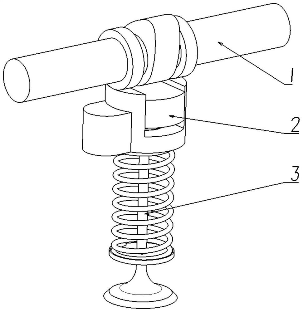
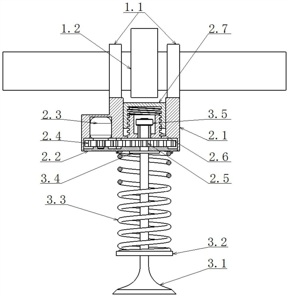
[0026] refer to Figure 1 to Figure 7 As shown, the cam direct-drive air distribution mechanism that realizes continuously variable engine valve lift in an embodiment provided by the present invention includes a camshaft 1, a lift adjustment mechanism 2 and a valve assembly 3, and the camshaft 1 is provided with Cam 1.2, the cam 1.2 is set above the lift adjustment mechanism 2, the cam 1.2 is in contact with the lift adjustment mechanism 2, the lift adjustment mechanism 2 is fixedly connected with the valve assembly 3, and the cam 1.2 drives the valve assembly through the lift adjustment mechanism 2 3 moves along the axial direction, the camshaft 1 is used to control the opening and closing of the engine valve, and the lift adjustment mechanism 2 is used to realize the stepless change of the valve lift.

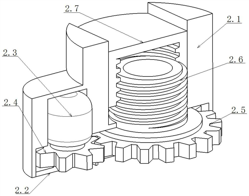
[0027] Further, the lift adjustment mechanism...


PUM


Abstract

The invention discloses a cam direct-drive type valve mechanism capable of realizing continuous variable valve lift of an engine. The mechanism comprises a cam shaft, a lift adjusting mechanism and avalve component, a cam is arranged on the cam shaft and is arranged above the lift adjusting mechanism, and the lift adjusting mechanism is fixedly connected with the valve component into a whole; andthe cam drives the valve assembly to move in the axial direction through the lift adjusting mechanism, the cam shaft is used for controlling opening and closing of an engine valve, and the lift adjusting mechanism is used for achieving stepless change of the valve lift. Stepless change of the valve lift of the engine is achieved, and the economical efficiency of the engine under the low-load working condition and the dynamic property of the engine under the high-load working condition are improved.

Description

technical field [0001] The invention relates to the technical field of automobile engines, in particular to a cam direct-drive valve mechanism for continuously variable engine valve lift. Background technique [0002] The engine valve lift is the axial displacement of the valve when the valve is fully open compared to when the valve is closed, indicating the maximum opening degree of the valve. The valve lift of the traditional engine is fixed. In order to take into account all the operating conditions as much as possible, the size of the valve lift is usually a compromise choice. Therefore, when the power demand is low, the valve lift is too large, and the engine economy becomes poor. , when the power demand is high, the valve lift is relatively small, and the engine power is not good. In order to allow the engine to have the most suitable valve lift under all working conditions, variable valve lift technology (VVL) emerged as the times require. Increase valve lift under ...

Claims


Application Information

Patent Timeline
IPC IPC(8): F01L13/00F01L1/053F01L9/04F01L3/10
CPCF01L1/053F01L3/10F01L13/00
Inventor 肖合林黄佳琦郭风云陈志鑫
Owner WUHAN UNIV OF TECH
Why Eureka
Try Eureka