Fan

A fan and shroud technology, applied in mechanical equipment, machines/engines, liquid fuel engines, etc., can solve the problems of complex assembly process, many parts and high cost, and achieve simple assembly process, few parts and low cost Effect

Pending Publication Date: 2020-11-03
北京日祥科技有限公司
View PDF0 Cites 0 Cited by
  • Summary
  • Abstract
  • Description
  • Claims
  • Application Information

AI Technical Summary

Problems solved by technology

[0004] The invention provides a fan, which is used to solve the technical problems of many parts, complicated assembly process and high cost in the fan in the prior art

Method used


Image

  • Fan
  • Fan
  • Fan

Examples


Embodiment 1

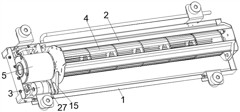
[0038] This embodiment provides a fan, which includes a frame 1, a wind deflector 2, a first motor 3, a blade assembly 4 and a second motor 5, wherein the first motor 3, the second motor 5 and the wind deflector 2 are installed on the frame 1, and the connection between the above-mentioned wind deflector 2 and the frame 1 is a rotational connection, and the wind deflector 2 is connected with the rotating shaft of the above-mentioned first motor 3, and the first motor 3 can drive the wind deflector 2 swings, the above-mentioned fan blade assembly 4 is arranged inside the wind deflector 2, the rotating shaft of the second motor 5 is connected with the blade assembly 4, and the second motor 5 will rotate inside the wind deflector 2 to generate wind when the second motor 5 is energized and running. The wind flows out of the blower fan after being diverted by the shroud 2 .

[0039] Specifically, a bearing seat 6 is installed on the side wall of the above-mentioned wind deflector 2...

Embodiment 2

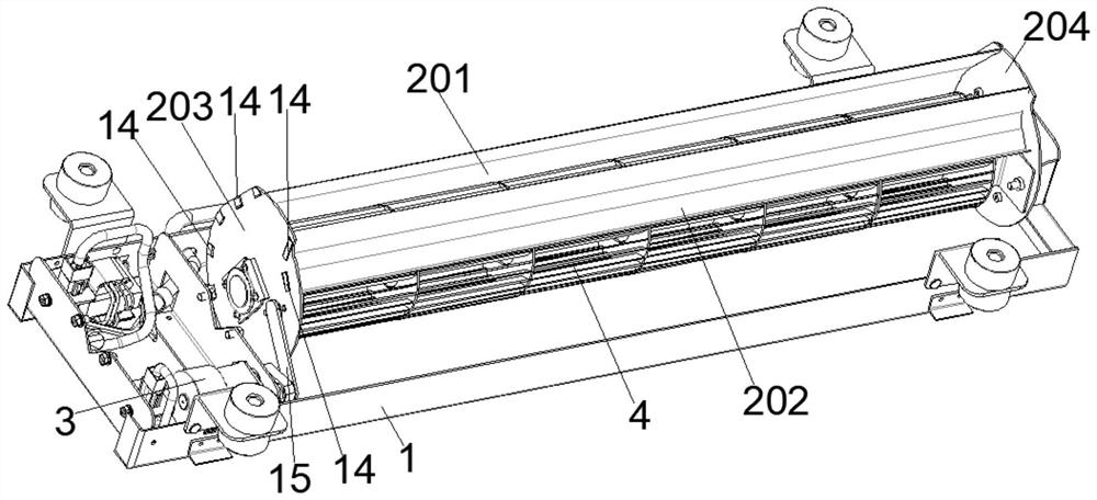
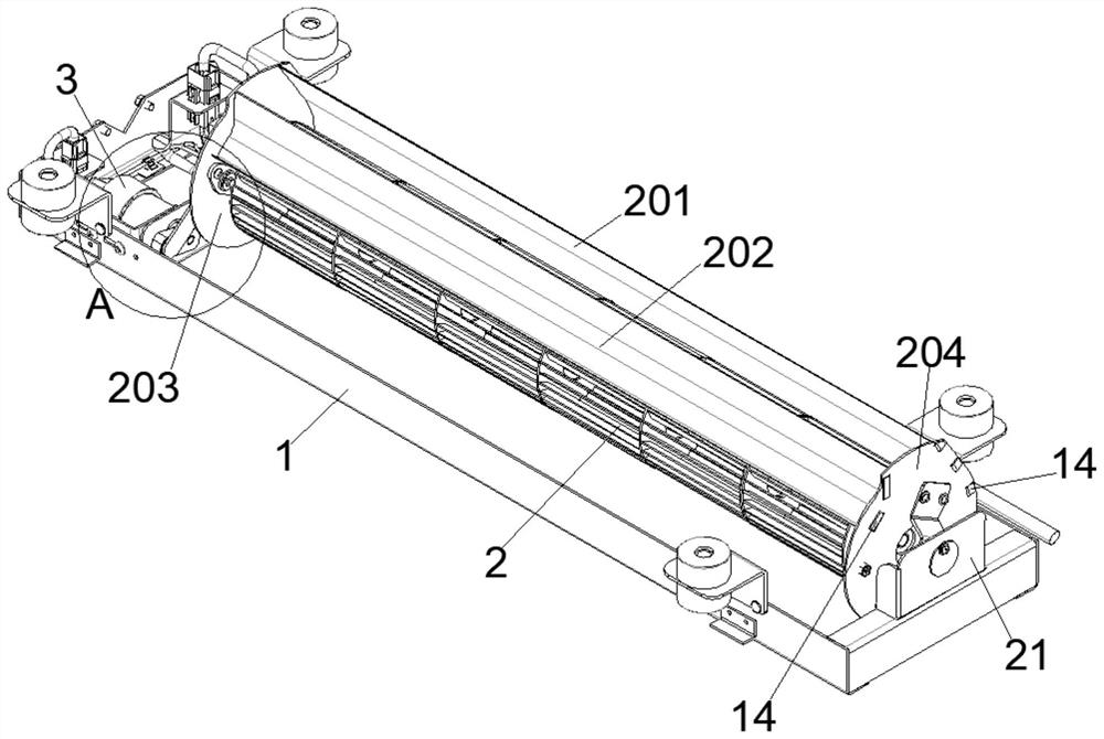
[0042] This embodiment serves as a specific implementation of Embodiment 1. In this embodiment, the above-mentioned wind deflector 2 includes a first wind deflector 201, a second wind deflector 202, a left side plate 203 and a right side plate 204, wherein , one end of the first deflector 201 and one end of the second deflector 202 are connected to the left side plate 203, the other end of the first deflector 201 and the other end of the second deflector 202 are connected to the right On the side plate 204, that is, the first deflector 201 and the second deflector 202 are connected between the left side plate 203 and the right side plate 204, and the first deflector 201 and the second deflector 202 are spaced apart. Set, the wind generated when the fan blade assembly 4 rotates is blown out from the gap between the first deflector 201 and the second deflector 202, when the first motor 3 drives the deflector 2 to swing as a whole, the above gap Rotate to control the wind directi...

Embodiment 3

[0045] This embodiment is used as a specific implementation of the embodiment. The fan provided by this embodiment also includes a first L-shaped plate 8, a second L-shaped plate 9 and a connecting plate 10, wherein the first L-shaped plate 8 and the second L-shaped plate 8 The pattern plate 9 is set away from, and the above-mentioned connection plate 10 is a flat plate, and the connection plate 10 is connected between the above-mentioned first L-shaped plate 8 and the second L-shaped plate 9. At this time, the above-mentioned first L-shaped plate 8, the connection plate 10 And the second L-shaped plate 9 forms a middle raised plate-like structure, and the above-mentioned first L-shaped plate 8 is detachably fixedly connected to the left side wall of the above-mentioned right side plate 204 by the first screw 11, and, in this The left side wall of right side plate 204 is also provided with column 12, and this column 12 protrudes left side wall of right side plate 204 toward the...


PUM


Abstract

The invention relates to a fan, and belongs to the technical field of fans. The fan comprises a frame, a flow guide cover and a first motor, the flow guide cover is rotatably mounted on the frame, thefirst motor is mounted in the frame, and a rotating shaft of the first motor is connected with the flow guide cover to drive the flow guide cover to swing; the fan further comprises a fan blade assembly and a second motor, the second motor is also installed in the frame, the fan blade assembly is arranged in the flow guide cover, one end of the fan blade assembly is connected with a rotating shaft of the second motor, a bearing seat is installed on the side wall of the flow guide cover, a bearing is installed on the bearing seat, and the other end of the fan blade assembly is in interferenceconnection with the bearing; and the bearing seat is a structural member made of a hard elastic material. By means of the structure, in the fan, the bearing seat has the effects of reducing vibrationand noise and aligning the rotation of the fan blade assembly, the functions are achieved without additionally installing components, the structure is simpler, the number of parts is smaller, and thecost is lower.

Description

technical field [0001] The invention belongs to the technical field of fans, in particular to a fan. Background technique [0002] Fans in the prior art usually include a blade assembly and a shroud. The blade assembly is driven by a motor to rotate, and the blade assembly is arranged inside the shroud. When it rotates, it can generate wind. After the wind is guided by the shroud blow out. [0003] One end of the fan blade assembly of an existing fan is rigidly connected to the motor, while the other end is rotatably inserted on the side wall of the shroud and driven by a bearing. A wave spring is arranged between the bearing and the side wall of the shroud. The buffering effect of the wave spring can achieve the effect of automatic centering and shock absorption and noise reduction when the fan assembly rotates. However, because the wave spring is an independent structure, this structure will cause the fan to have many parts and the assembly process is responsible. and th...

Claims


Application Information

Patent Timeline
Patent Type & Authority Applications(China)
IPC IPC(8): F04D25/08F04D29/44F04D29/00F04D29/056F04D29/66A61L9/20A61L9/22
CPCA61L9/20A61L9/22F04D25/08F04D29/002F04D29/0563F04D29/441F04D29/668
Inventor 崔辰睿崔长在赵晋龙谢玉林周晔王宏宝
Owner 北京日祥科技有限公司
Why Eureka
Try Eureka