New energy motor shell positioning gripper

A motor housing and new energy technology, which is applied in the manufacture of motor generators, electromechanical devices, electrical components, etc., can solve the problems of poor motor housing grabbing effect and inaccurate positioning grabbing, and achieve grabbing effect. Good, high grabbing efficiency, easy grabbing effect

Active Publication Date: 2020-11-03
无锡泓阳电动科技有限公司
View PDF6 Cites 4 Cited by
  • Summary
  • Abstract
  • Description
  • Claims
  • Application Information

AI Technical Summary

Problems solved by technology

[0005] Aiming at the deficiencies of the prior art, the present invention provides a new energy motor housing positioning gripper, mainly to solve the problem of inaccurate positioning and grasping, and poor grasping effect on motor housings of different sizes

Method used


Image

  • New energy motor shell positioning gripper
  • New energy motor shell positioning gripper
  • New energy motor shell positioning gripper

Examples


Embodiment 1

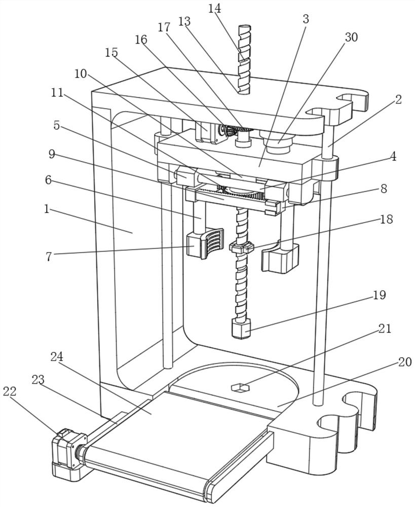
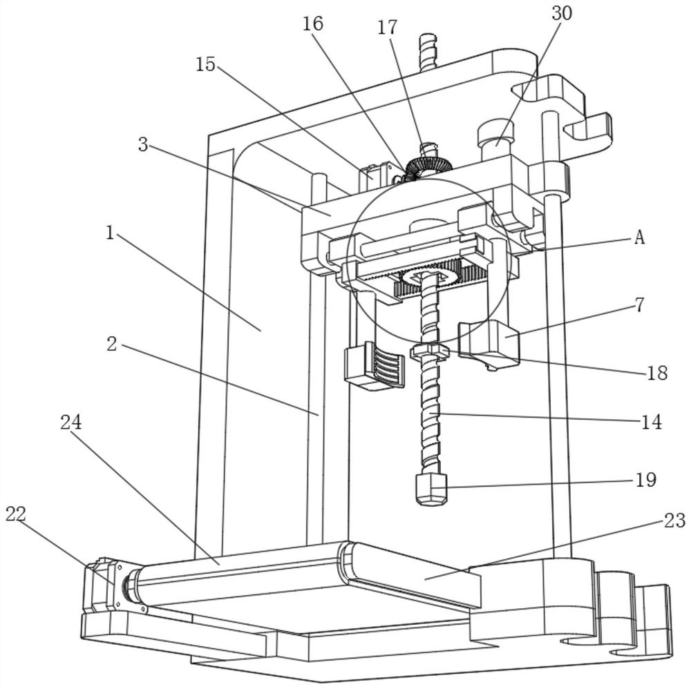
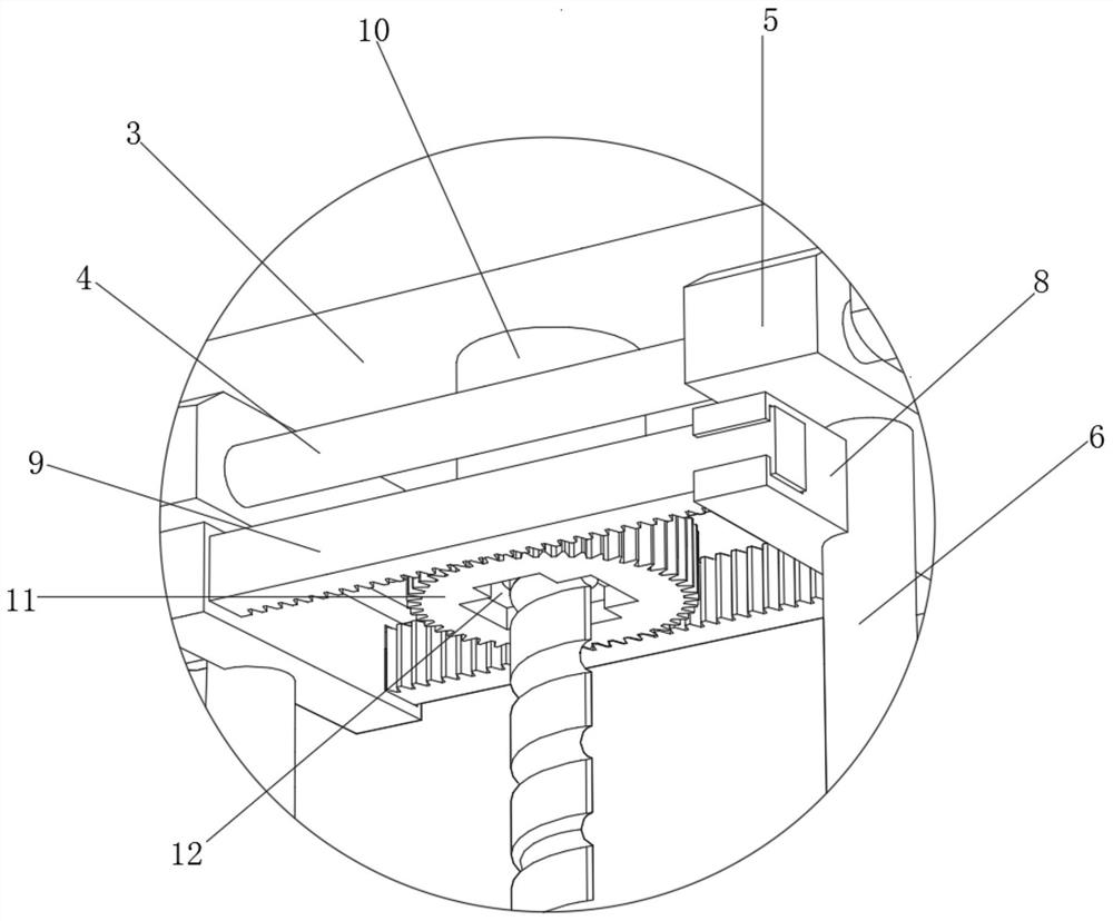
[0029] refer to Figure 1-Figure 4 , a new energy motor shell positioning gripper, including a support frame 1, two guide rods 2 are fixed by bolts in the support frame 1, and the outer walls of the guide rods 2 are slidably connected to the same installation block 3, and the installation block 3 Two sliding shafts 4 are fixed on the bottom by bolts, and two sliders 5 are slidably connected to one side of the outer wall of the sliding shafts 4, and the bottom side of the sliders 5 is fixed to a connecting column 6 by bolts, and the bottom of the connecting columns 6 all pass through Bolts are fixed with clamping blocks 7, and one side of the connecting column 6 is fixed with two fixed blocks 8 by bolts, and one side of the fixed blocks 8 is fixed with a rack 9 by bolts, and one side of the mounting block 3 is rotatably connected with a rotating column 10. And one side of the bottom end of the rotating column 10 is fixed with a rotating gear 11 by a bolt, and the cooperative us...

Embodiment 2

[0033] refer to Figure 5 , a new energy motor housing positioning gripper, including a connecting block 28 fixed to the bottom end of the connecting column 6 by bolts, and a plugging slot 29 is opened on one side of the connecting block 28, and a plugging slot 29 is inserted into the plugging slot 29. Connecting block 27, the other side of plugging block 27 is fixed with arc splint 26 by bolt, and the setting of splicing block 27 on the arc splint 26 and the insertion groove 29 on the connection block 28 can facilitate the replacement of arcs of different sizes. Shaped splint 26, so as to be able to better accurately grasp motor housings of different sizes, so as to better improve the grasping efficiency.

[0034] The working principle of this embodiment: when in use, when it is necessary to grab motor housings of different sizes, pull out the plug-in block 27 on the arc splint 26 from the slot 29 on the connection block 28, thereby replacing the arc splint 26. Grab motor ca...


PUM


Abstract

The invention relates to the technical field of new energy motor assembly, and discloses a new energy motor shell positioning gripper which comprises a supporting frame. Two guide rods are fixed in the supporting frame through bolts, the outer walls of the guide rods are slidably connected with a same mounting block, and two sliding shafts are fixed to the bottom of the mounting block through bolts. Two sliding blocks are slidably connected to one side of the outer wall of each sliding shaft, a connecting column is fixed to one side of the bottom of each sliding block through a bolt, a clamping block is fixed to the bottom of each connecting column through a bolt; two fixing blocks are fixed to one side of each connecting column through bolts, and a rack is fixed to one side of each fixingblock through a bolt; and a rotating column is rotatably connected to one side of the mounting block. According to the gripper, the positioning and grabbing automation degree is high, the grabbing effect is good, the positioning and grabbing precision can be better improved, motor shells of different sizes can be better and accurately grabbed, and therefore the grabbing efficiency can be better improved.

Description

technical field [0001] The invention relates to the technical field of new energy motor assembly, in particular to a positioning gripper for a new energy motor housing. Background technique [0002] As we all know, the new energy motor housing positioning gripper is a positioning gripper that can accurately locate and grasp the new energy housing, and can detect the grasping state of the housing. It has been obtained in the field of It has been widely used; the existing new energy motor housing positioning gripper is found to have poor positioning effect and complicated structure. [0003] After retrieval, the authorized publication number is CN107127778A patent, which discloses a positioning gripper applied to the positioning and gripping process of new energy motor shells. It is composed of main parts such as tight plate, rotating support arm, three-jaw chuck, rotating cylinder, pressure displacement sensor and so on. There are following deficiencies in the above-mention...

Claims


Application Information

Patent Timeline
Patent Type & Authority Applications(China)
IPC IPC(8): H02K15/14
CPCH02K15/14
Inventor 陈泓
Owner 无锡泓阳电动科技有限公司
Why Eureka
Try Eureka