Machining equipment with cleaning function

A mechanical processing and equipment technology, applied in the field of mechanical processing equipment with cleaning function, can solve the problems of increasing the workload of processing personnel, affecting the efficiency of mechanical processing, etc., and achieves the effect of convenient and fast application and improved application effect.

Inactive Publication Date: 2020-11-06
SUZHOU KAIENAO AUTOMATION CO LTD
View PDF0 Cites 1 Cited by
  • Summary
  • Abstract
  • Description
  • Claims
  • Application Information

AI Technical Summary

Problems solved by technology

[0003] During mechanical processing, a large amount of impurities such as iron filings are often produced. When there are too many impurities, they will accumulate in large quantities and affect the processing. If cleaning is re

Method used


Image

  • Machining equipment with cleaning function
  • Machining equipment with cleaning function
  • Machining equipment with cleaning function

Examples


Embodiment 1

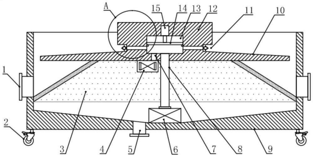
[0020] see figure 1 and 5 , in the embodiment of the present invention, a kind of mechanical processing equipment with cleaning function comprises processing box 9, and the inner side of described processing box 9 is provided with annular bottom plate 10, and the upper side of annular bottom plate 10 is fixed with processing table 12, and processing The lower outer ring of the table 12 is provided with an annular groove 11, and a plurality of flushing and exhausting heads 16 are installed in the circumferential direction of the annular groove 11. The inner side of the processing table 12 is also provided with a pressure relief chamber 13, and a plurality of flushing and exhausting heads 16 are provided. The lower part of the pressure relief chamber 13 is respectively communicated with the lower part of the pressure relief chamber 13 through the branch pipe 17. A pressure relief device for depressurizing the pressure relief chamber 13 is also installed in the processing table 1...

Embodiment 2

[0023] see Figure 1-5 , the difference between this embodiment and embodiment 1 is:

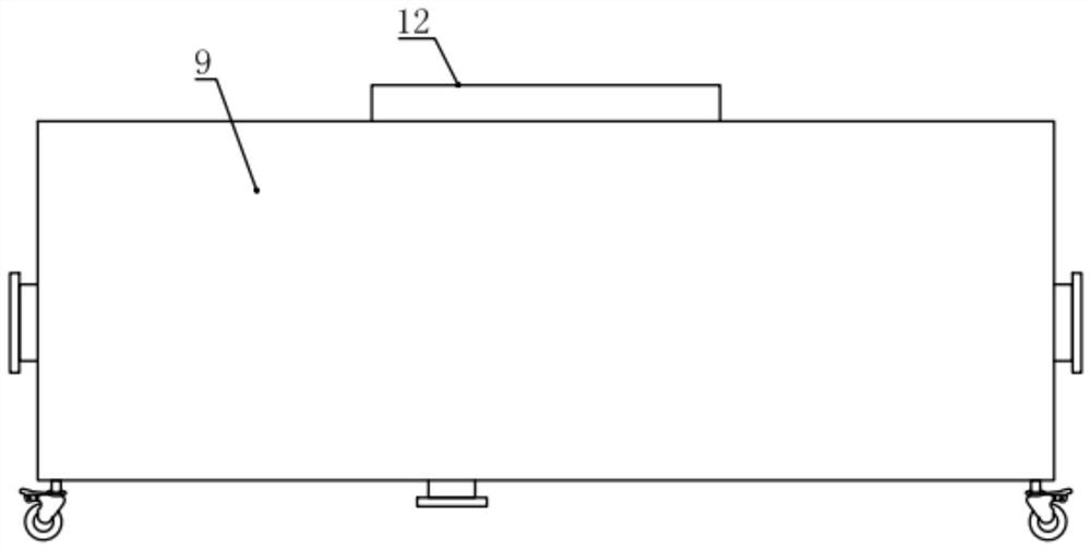
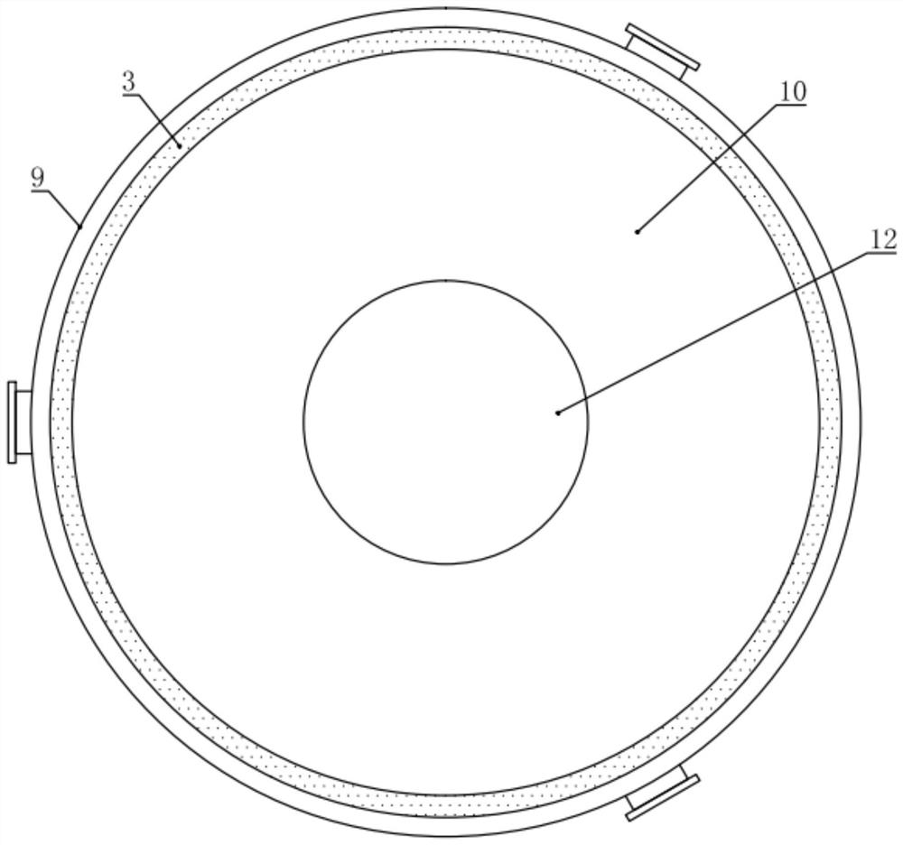
[0024] In the present embodiment, the processing box 9 is a cylindrical barrel structure with an upper opening, and the inner bottom of the processing box 9 is arranged downward in the middle; the processing table 12 is a cylindrical structure, and the annular bottom plate 10 is a circle. Disc-shaped structure, and the processing table 12, the annular bottom plate 10 and the processing box 9 are coaxially arranged, and the processing table 12 and the annular bottom plate 10 are integrally processed and formed; the upper surface of the annular bottom plate 10 is set with an outer ring inclined downward, which is beneficial to impurities The vertical distance between the outer ring of the annular bottom plate 10 and the inner wall of the processing box 9 is less than 5cm, and the impurities can fall.

[0025] The miscellaneous net cylinder 3 is a tapered cylinder structure with a small top an...


PUM


Abstract

The invention relates to the field of machining equipment, in particular to machining equipment with a cleaning function. The equipment comprises a machining box body, an annular bottom plate is arranged on the inner side of the machining box body, a machining table is fixed on the upper side of the annular bottom plate, an annular groove is formed in the outer ring of the lower side of the machining table, and a plurality of flushing exhaust heads are mounted in the annular groove; a pressure relief cavity is further formed in the inner side of the machining table, the multiple flushing exhaust heads communicate with the lower portion of the pressure relief cavity through branch pipes correspondingly, a pressure relief device used for relieving pressure of the pressure relief cavity is further installed in the machining table, a flushing pump is installed at the inner bottom of the machining box and communicates with the bottom of the pressure relief cavity through a water conveying pipe, a temperature control draught fan is further installed on the lower side of the annular bottom plate and communicates with the bottom of the pressure relief cavity through an air conveying pipe,an impurity blocking net barrel is further installed on the lower side of the annular bottom plate, and the lower end of the impurity blocking net barrel is fixed to the inner side wall of the machining box body. The device is novel in structure, machining impurities can be conveniently and rapidly removed, and popularization is facilitated.

Description

technical field [0001] The invention relates to the field of mechanical processing equipment, in particular to a mechanical processing equipment with a cleaning function. Background technique [0002] Machining refers to the process of changing the shape or performance of a workpiece through a mechanical device. According to the difference in processing method, it can be divided into cutting processing and pressure processing. [0003] During mechanical processing, a large amount of impurities such as iron filings are often produced. When there are too many impurities, they will accumulate in large quantities and affect the processing. If cleaning is required, the processing work needs to be stopped, and then the impurities are brushed away and stored with a brush. This operation It not only affects the efficiency of mechanical processing, but also increases the workload of processing personnel. [0004] Therefore, in view of the above status quo, it is urgent to develop a...

Claims


Application Information

Patent Timeline
IPC IPC(8): B08B3/02F26B21/00
CPCB08B3/02F26B21/00
Inventor 柳明观
Owner SUZHOU KAIENAO AUTOMATION CO LTD
Why Eureka
Try Eureka