Hot-molten metal micro-droplet direct on-demand printing mechanism based on piezoelectric micro jetting

A printing mechanism and micro-droplet technology, applied in the direction of improving process efficiency, additive processing, and improving energy efficiency, can solve the problems of low precision of molten metal droplet printing, complicated manufacturing process, and low material utilization rate. Achieve the effects of low cost, simple and compact structure, and no electromagnetic interference

Active Publication Date: 2020-11-06
哈尔滨浩星科技有限公司
View PDF20 Cites 0 Cited by
  • Summary
  • Abstract
  • Description
  • Claims
  • Application Information

AI Technical Summary

Problems solved by technology

[0003] In view of this, the present invention aims to propose a direct on-demand printing mechanism of hot-melt metal micro-droplets based on piezoelectric micro-spraying. The present invention can realize direct printing and jetting of hot-melt metal micro-droplets. The pressure system only relies on gravity to make the molten metal continuously flow into the cavity along the liquid supply channel. The shape of the sprayed hot melt metal micro-droplets is regular, and the exit speed and volume are controllable. The problem of complex material manufacturing process and low material utilization rate and the low precision, complex structure and slow response of the pneumatic-based molten metal droplet printing method

Method used


Image

  • Hot-molten metal micro-droplet direct on-demand printing mechanism based on piezoelectric micro jetting
  • Hot-molten metal micro-droplet direct on-demand printing mechanism based on piezoelectric micro jetting
  • Hot-molten metal micro-droplet direct on-demand printing mechanism based on piezoelectric micro jetting

Examples


Embodiment Construction

[0037] It should be noted that the embodiments of the present invention and the features in the embodiments can be combined with each other if there is no conflict.

[0038] Hereinafter, the present invention will be described in detail with reference to the drawings and in conjunction with the embodiments.

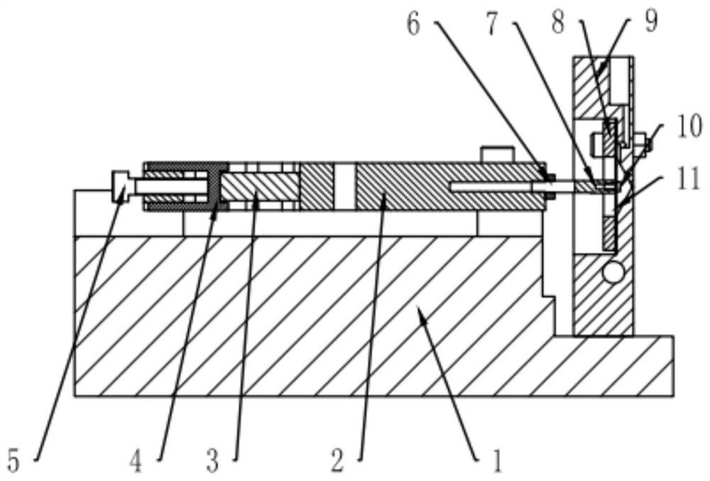
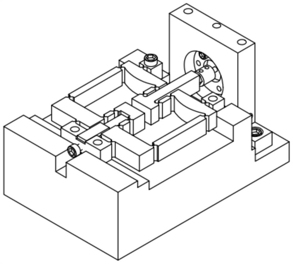
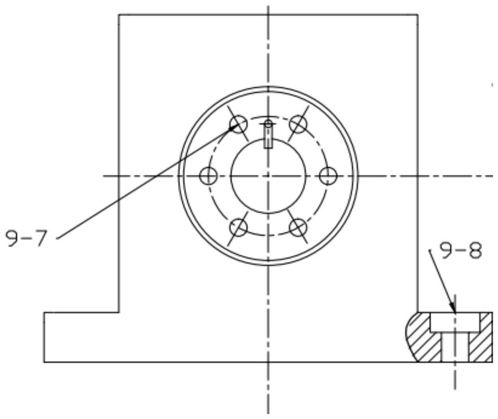
[0039] Such as Figure 1-Figure 8 As shown, a direct-on-demand printing mechanism for hot-melt metal micro-droplets based on piezoelectric micro-jets includes a base 1, a flexible displacement amplification mechanism 2, a piezoelectric stack 3, a guide compression block 4, a push rod 7, The rigid compression ring 8, the hot-melt cavity structure 9 and the elastic diaphragm 11, the flexible displacement amplification mechanism 2 and the hot-melt cavity structure 9 are all fixed on the base 1 by bolts, in the hot-melt cavity The center of the structure 9 is provided with a cone-shaped cavity 9-5, and the opening of the cone-shaped cavity 9-5 is arranged toward the output end of ...


PUM


Abstract

The invention provides a hot-molten metal micro-droplet direct on-demand printing mechanism based on piezoelectric micro jetting. The mechanism comprises a base, a flexible displacement amplificationmechanism, a piezoelectric stack, a push rod, a rigid pressing ring, a hot melting cavity structure and an elastic membrane. The flexible displacement amplification mechanism and the hot melting cavity structure are both fixed to the base. A conic cavity is formed in the center of the hot melting cavity structure. A feeding hole is formed in the upper wall face of the hot melting cavity structureand communicates with the conic cavity through a communicating groove channel. A jetting micropore is formed in the pointed end of the conic cavity. The piezoelectric stack is connected with the inputend of the flexible displacement amplification mechanism. One end of the push rod is connected with the output end of the flexible displacement amplification mechanism, and the other end of the pushrod is connected with the elastic membrane. The rigid pressing ring presses the elastic membrane to cover an opening of the conic cavity to form a closed cavity. By means of the mechanism, direct printing and jetting of hot-molten metal micro-droplets can be achieved, the structure is simple and compact, the shapes of jetted hot-molten metal micro-droplets are regular, and the outlet speed and size can be controlled.

Description

Technical field [0001] The invention belongs to the field of hot-melt metal micro-droplet jetting, and in particular relates to a direct-on-demand printing mechanism for hot-melt metal micro-droplets based on piezoelectric micro jetting. Background technique [0002] At present, the hot-melt metal micro-droplet jet printing technology has good application prospects in the repair of small defects in metal parts, the printing and molding of micro-complex metal structures, and the soldering of electronic components. The existing uniform molten metal jet deposition technology has a relatively complicated method for accurately controlling the ejected continuous fluid, and it is difficult to achieve on-demand injection. It is generally used for high-frequency continuous jet deposition manufacturing; in addition, the existing melting based on pneumatic drive The metal droplet ejection method is limited by the compressibility of the gas, and has the disadvantages of poor control effect, ...

Claims


Application Information

Patent Timeline
IPC IPC(8): B22F3/115B33Y30/00
CPCB22F3/115B33Y30/00Y02P10/25
Inventor 李锴刘英想陈维山刘军考
Owner 哈尔滨浩星科技有限公司
Why Eureka
Try Eureka