Mold injection molding equipment for producing illuminating apparatus

A technology of injection molding equipment and illuminators, which is applied in the field of mold injection molding equipment for illuminators production, can solve problems such as automatic demoulding and collection of inconvenient molded parts, low molding efficiency of injection molded parts, and fixed and rigid overall structure, so as to improve molding processing efficiency , good heat preservation effect and high degree of automation

Inactive Publication Date: 2020-11-06
嘉兴市光炬五金科技有限公司
View PDF27 Cites 0 Cited by
  • Summary
  • Abstract
  • Description
  • Claims
  • Application Information

AI Technical Summary

Problems solved by technology

[0003] The overall structure of the existing mold injection molding equipment is relatively fixed and rigid. When using it, it is necessary to manually control the injection head to inject materials into the injection port of the mold, which is time-consuming and laborious, and increases the cost of manual operation. The existing mold injection molding equipment is not convenient for molding parts. Automatic demoulding and collection, the molding efficiency of injection molded parts is relatively low. Therefore, we propose a mold injection equipment for lighting production

Method used


Image

  • Mold injection molding equipment for producing illuminating apparatus
  • Mold injection molding equipment for producing illuminating apparatus
  • Mold injection molding equipment for producing illuminating apparatus

Examples


Embodiment Construction

[0020] The following will clearly and completely describe the technical solutions in the embodiments of the present invention with reference to the accompanying drawings in the embodiments of the present invention. Obviously, the described embodiments are only some, not all, embodiments of the present invention. Based on the embodiments of the present invention, all other embodiments obtained by persons of ordinary skill in the art without making creative efforts belong to the protection scope of the present invention.

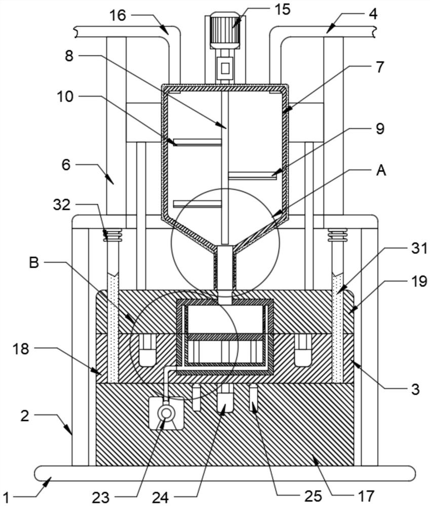
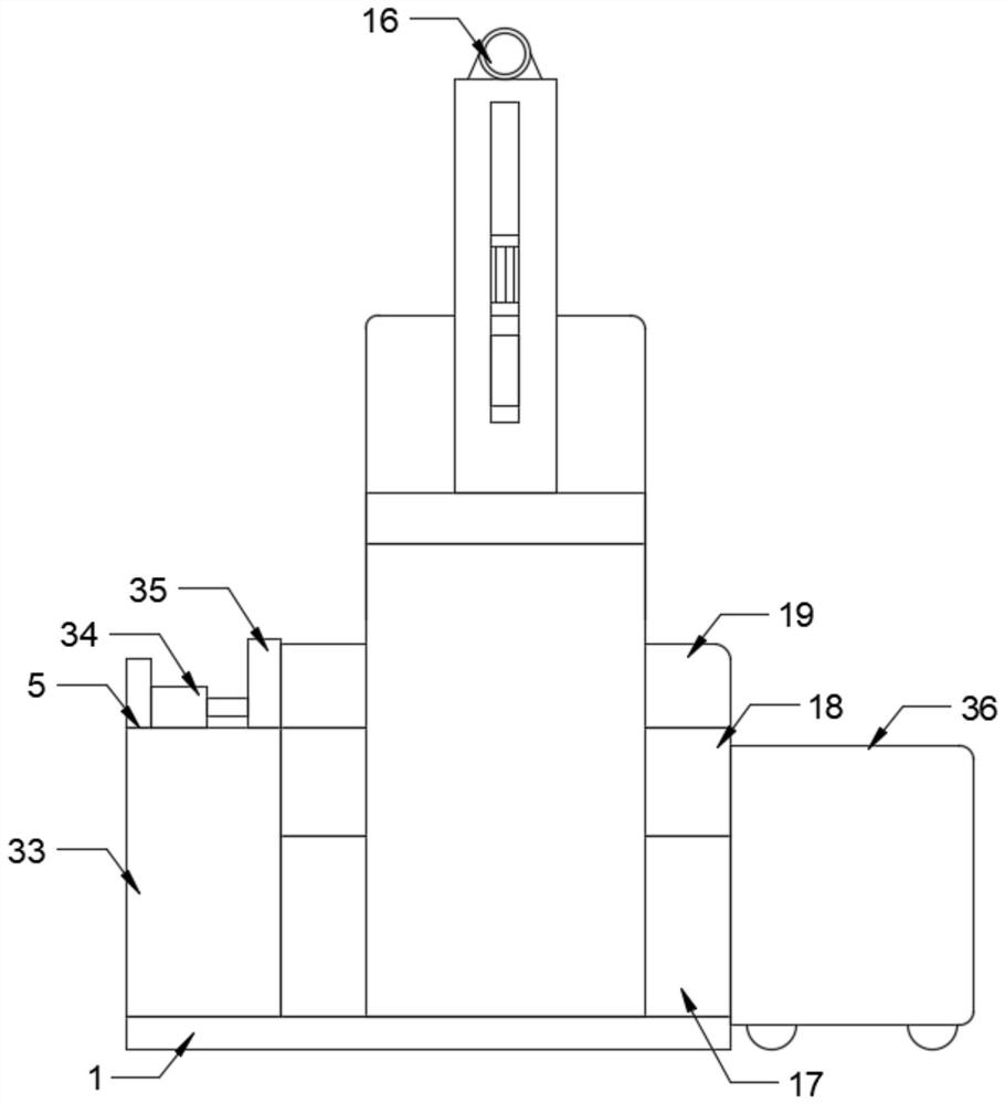
[0021] see figure 1 and figure 2 , the present invention provides a technical solution: a mold injection molding equipment for the production of illuminator components, including a base 1, a support frame 2 and an injection molding mechanism 3, a support frame 2 is installed on the top of the base 1, and the base 1. The top of the support frame 2 is provided with an injection molding mechanism 3. The top of the support frame 2 is provided with a feeding mech...


PUM


Abstract

The invention discloses mold injection molding equipment for producing an illuminating apparatus. The equipment comprises a base, a supporting frame and an injection molding mechanism, wherein the supporting frame is installed at the top of the base, the injection molding mechanism is arranged at the portion, located in the supporting frame, of the top of the base, a feeding mechanism is arrangedat the top of the supporting frame, a pushing mechanism and a collecting trolley are arranged at the portion, located at the two sides of the injection molding mechanism, of the top of the base respectively, the injection molding mechanism comprises a base, a fixed plate and a top plate, the base is installed at the top of the base, the fixed plate is installed at the top of the base, the top plate is connected to the top of the fixed plate, a feeding port is formed in the top of the top plate, an upper template is embedded in the bottom of the top plate, a lower template is embedded in the top of the fixed plate, and a mold cavity is formed between the lower template and the upper template and communicates with the feeding port. The mold injection molding equipment for producing the illuminating apparatus is simple in overall structure, capable of saving time and labor and high in degree of automation, and the efficiency of molding parts of the illuminating apparatus is greatly improved.

Description

technical field [0001] The invention relates to the technical field of mold injection molding equipment, in particular to a mold injection molding equipment for lighting production. Background technique [0002] The illuminator is a device that redistributes the luminous flux emitted by the light source and prevents the human eye from being affected by strong light according to people's requirements for lighting quality. It includes light sources, optical devices to control the direction of light, components necessary to fix and protect the bulb and connect to the power supply, components for decoration, adjustment and installation, etc., commonly known as illuminators, and the components that need to be used for the production of illuminators pass through molds Perform injection molding. [0003] The overall structure of the existing mold injection molding equipment is relatively fixed and rigid. When using it, it is necessary to manually control the injection head to inje...

Claims


Application Information

Patent Timeline
Patent Type & Authority Applications(China)
IPC IPC(8): B29C45/03B29C45/46B29C45/74B29C45/17
CPCB29C45/03B29C45/46B29C45/74B29C45/1769B29C2045/177B29L2031/747
Inventor 夏枫
Owner 嘉兴市光炬五金科技有限公司
Why Eureka
Try Eureka