
Carbon dioxide laser cutting machine rack with automatic feeding mechanism

A technology of laser cutting machine and carbon dioxide, which is applied in the direction of laser welding equipment, welding/cutting auxiliary equipment, manufacturing tools, etc., can solve the problems of waste of human resources, failure to improve efficiency, manual feeding, etc., and achieve the effect of reducing labor cost

Inactive Publication Date: 2020-11-24
苏州刘氏钣金科技有限公司
View PDF0 Cites 2 Cited by
  • Summary
  • Abstract
  • Description
  • Claims
  • Application Information

AI Technical Summary

Problems solved by technology

However, the common carbon dioxide lasers on the market now often require manual feeding and angle adjustment, which will consume unnecessary manpower, waste human resources and fail to improve efficiency.

Method used


Image

  • Carbon dioxide laser cutting machine rack with automatic feeding mechanism
  • Carbon dioxide laser cutting machine rack with automatic feeding mechanism
  • Carbon dioxide laser cutting machine rack with automatic feeding mechanism

Examples


Embodiment Construction

[0022] In order to make the technical means, creative features, achievement goals and effects realized by the present invention easy to understand, the present invention will be further described below with reference to the specific embodiments.

[0023] In the description of the present invention, it should be noted that the terms "upper", "lower", "inner", "outer", "front end", "rear end", "two ends", "one end" and "the other end" The orientation or positional relationship indicated by etc. is based on the orientation or positional relationship shown in the accompanying drawings, and is only for the convenience of describing the present invention and simplifying the description, rather than indicating or implying that the indicated device or element must have a specific orientation, with a specific orientation. The orientation configuration and operation are therefore not to be construed as limitations of the present invention. Furthermore, the terms "first" and "second" are...


PUM


Abstract

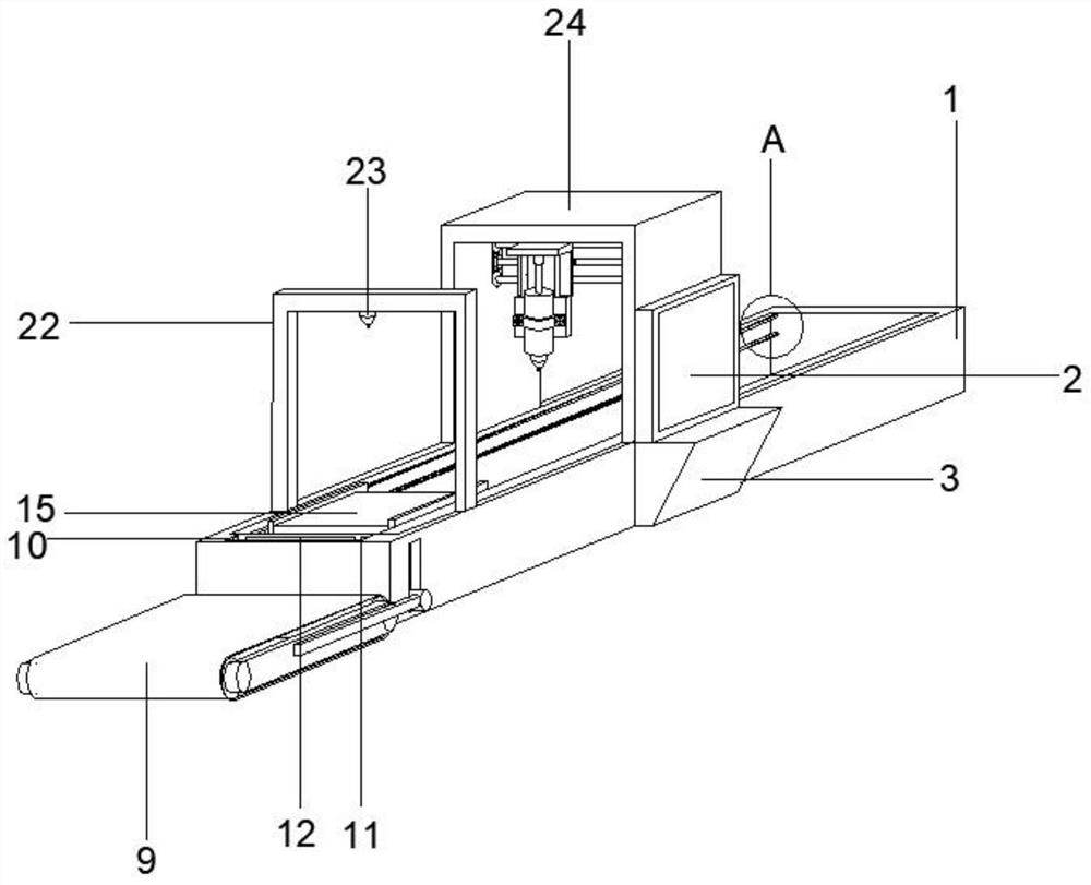
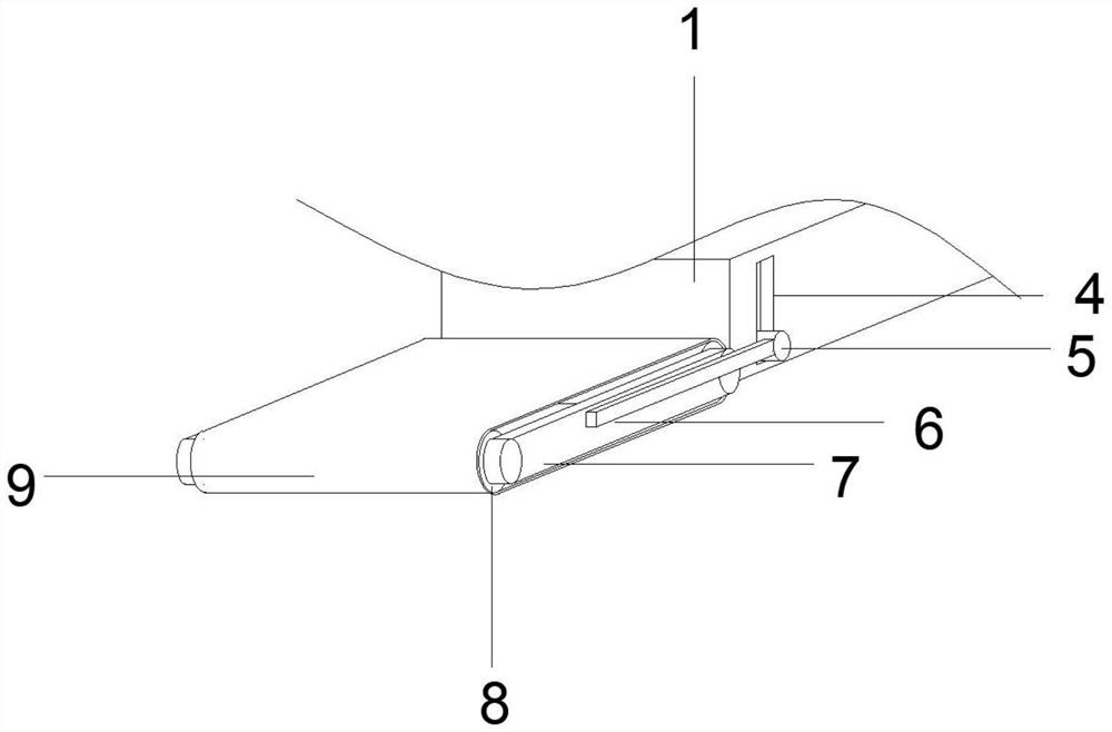
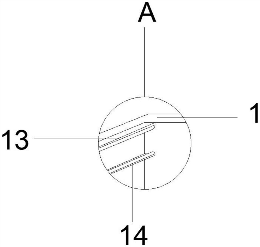
The invention discloses a carbon dioxide laser cutting machine rack with an automatic feeding mechanism. The carbon dioxide laser cutting machine rack comprises a cutting machine body, wherein a conveying belt is movably arranged on the front portion of the cutting machine body; a containing plate is movably installed inside the cutting machine body; the corresponding containing plate is arrangedon the front portion of the upper surface of the cutting machine body; a red point positioning device is fixedly installed above the upper surface of the containing plate; and a cutting support is movably installed in the middle of the upper surface of the cutting machine body. The carbon dioxide laser cutting machine rack with the automatic feeding mechanism belongs to the technical field of laser cutting, a lifting groove, a movable rod and a fixed rod are arranged to be matched so that the whole conveying belt device can move up and down, and automatic feeding of the cutting machine body isfacilitated; and an arranged abutting block enables a sliding shaft to help the conveying belt to transfer materials needing to be cut to the containing plate, and the red point positioning device isarranged to determine the material position, and then movable fixing plates on the left side and the right side of the containing plate are used for fixing and adjusting the material position.

Description

technical field [0001] The invention relates to the technical field of laser cutting, in particular to a carbon dioxide laser cutting machine frame with an automatic feeding mechanism. Background technique [0002] The carbon dioxide laser is a gas molecular laser, and the working substance is CO 2 Gases, auxiliary gases include nitrogen, helium, xenon and hydrogen, etc. Since the energy conversion efficiency of this laser is as high as 25%, it is often used as a high-power output laser. The carbon dioxide laser has a wavelength of 10.6 microns, which is impossible to see. Infrared light, stable better and widely used. However, the common carbon dioxide lasers on the market now often require manual feeding and angle adjustment, which will consume unnecessary manpower, waste human resources and fail to improve efficiency. So now we need a carbon dioxide laser rack that can automatically load materials and perform integrated positioning and cutting at the same time to reduce...

Claims


Application Information

Patent Timeline
Patent Type & Authority Applications(China)
IPC IPC(8): B23K26/38B23K26/70B23K37/04B23K26/08
CPCB23K26/0876B23K26/38B23K37/0426B23K26/702
Inventor 刘汉英
Owner 苏州刘氏钣金科技有限公司
Learn More