Winding device for circuit laying

A winding device and circuit technology, which is applied in the directions of transportation and packaging, thin material processing, and filamentary material transportation, can solve the problems of reducing the transmission efficiency of the rotating shaft, increasing the rotational friction force, and accumulating too much dust, so as to achieve convenient Clean operation, efficient lubrication, ensure the effect of normal work

Inactive Publication Date: 2020-11-06
国网内蒙古东部电力有限公司建设分公司 +1
View PDF11 Cites 1 Cited by
  • Summary
  • Abstract
  • Description
  • Claims
  • Application Information

AI Technical Summary

Problems solved by technology

[0003] For example, a winding device for electric wire production disclosed in the invention with the authorized announcement number CN207932772U, although it realizes the transmission effect through the MYT3-23 hydraulic pusher, it can control the movement of the push plate, thereby changing the distance between the push plate and the baffle plate. The distance between wires can be adjusted to achieve the purpose of adjusting the width of the wire. After the wire is wound, the wire can also be pushed out through the push plate to facilitate retrieving; such as a wire winding device for a network power transformer disclosed in an invention with the authorization announcement number CN207947165U. Although the structure is simple and the operation is convenient, the winding motor is not only easy to install, but also through the positioning column and the positioning hole, the winding motor is installed stably, which is beneficial to maintain the normal operation of the winding motor; The rotating friction force on the frame becomes larger, which reduces the transmission efficiency of the rotating shaft; in addition, when the device is used for a long time, too much dust accumulates on the rotating end of the rotating shaft and the supporting frame, which is inconvenient to clean; The vibration generated during the operation of the device has the problem of damage to the components on the device. For this reason, we propose a winding device for circuit laying

Method used


Image

  • Winding device for circuit laying
  • Winding device for circuit laying
  • Winding device for circuit laying

Examples


Embodiment Construction

[0025] The following will clearly and completely describe the technical solutions in the embodiments of the present invention with reference to the accompanying drawings in the embodiments of the present invention. Obviously, the described embodiments are only some, not all, embodiments of the present invention. Based on the embodiments of the present invention, all other embodiments obtained by persons of ordinary skill in the art without making creative efforts belong to the protection scope of the present invention.

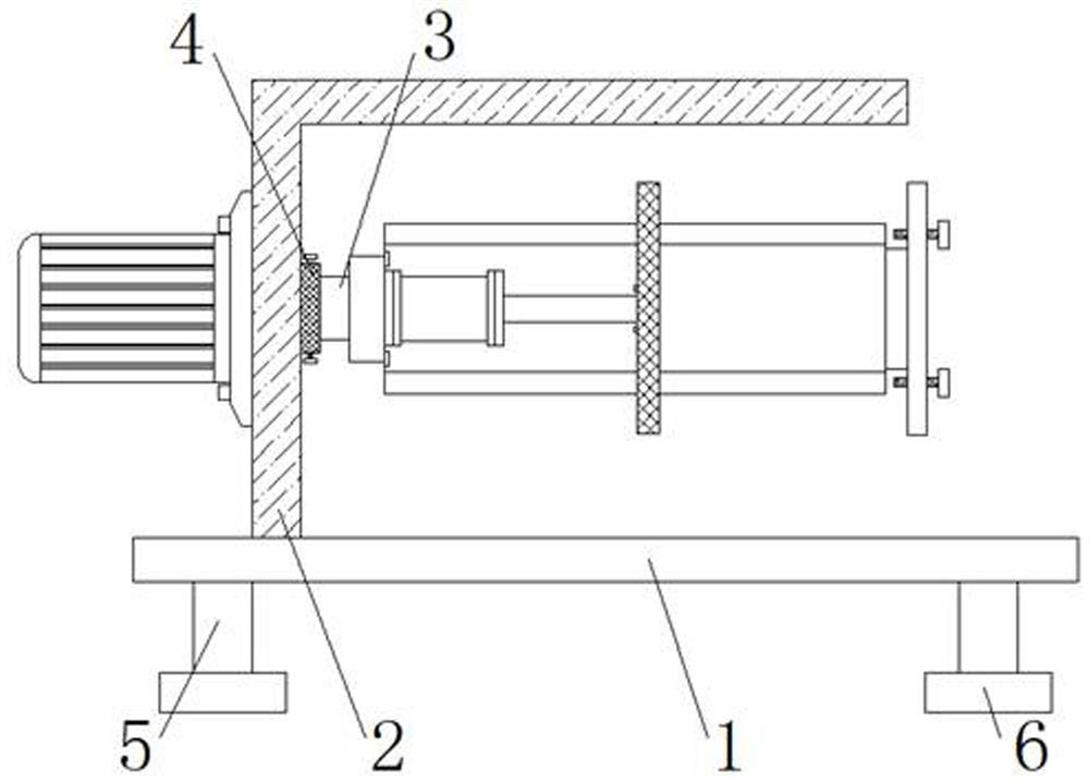
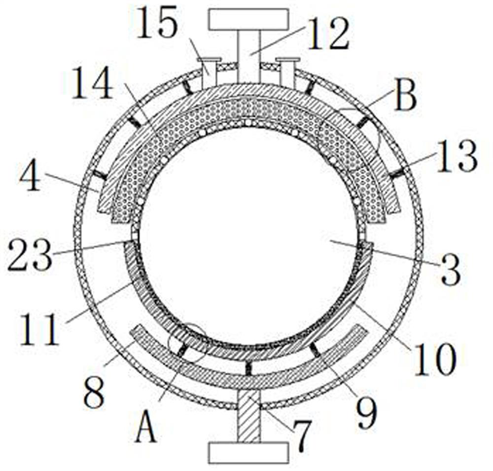
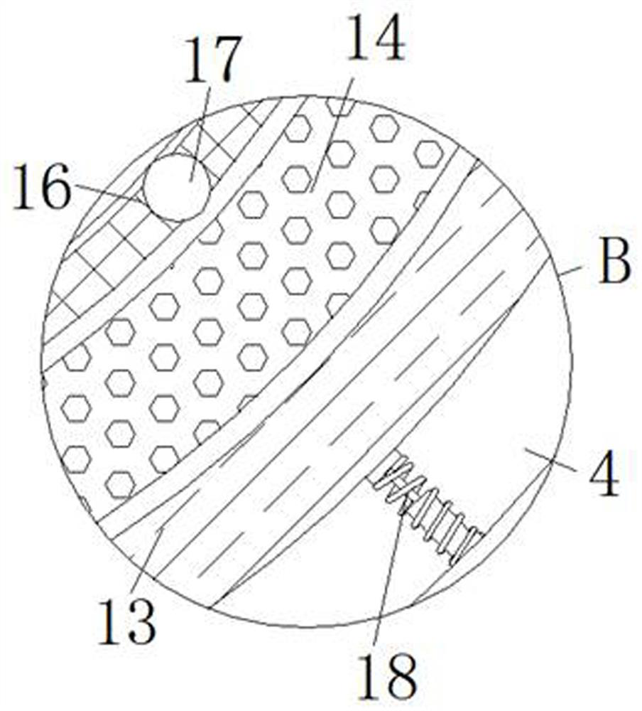
[0026] see Figure 1-Figure 5 , the present invention provides a technical solution: a winding device for circuit laying, including a bottom plate 1, a support frame 2 is fixed on the top of the bottom plate 1, a motor is fixed on one side surface of the support frame 2, and the output shaft of the motor is rotatably connected to a rotating shaft 3 The rotation of the rotating shaft 3 is transmitted to the inner side of the supporting frame 2 and the end is fi...


PUM


Abstract

The invention discloses a winding device for circuit laying. The winding device for circuit laying comprises a bottom plate, wherein a support frame is fixed to the top end of the bottom plate; a motor is fixed to the surface of one side of the support frame; a rotary shaft is rotationally connected to the output shaft of the motor; the rotation of the rotary shaft is transmitted to the inner sideof the support frame and a winding reel is fixed to the tail end of the rotary shaft; a fixed sleeve is fixedly connected to the support frame and the rotary end of the rotary shaft in a sleeved manner; a push rod movably penetrates into the outer wall of the fixed sleeve; the push rod extends into an empty cavity of the fixed sleeve and a push plate is fixed to the tail end of the push rod; an extrusion spring is arranged at the junction of the push plate and the empty cavity of the fixed sleeve; and a sponge block is arranged on the surface of one side of the push plate. Through the arranged sponge block, convenient and efficient lubrication for the surface of the rotary shaft is benefited; through an arranged brush head, convenient and rapid cleaning for dust and other impurities on the surface of the rotary shaft is benefited; and through an arranged limit plate, a guarantee on the normal working of the device is benefited, buffering for vibration of the device during working is facilitated, and the stability of the device is improved.

Description

technical field [0001] The invention belongs to the technical field of winding devices, and in particular relates to a winding device for circuit laying. Background technique [0002] A conductive loop composed of metal wires and electrical and electronic components is called a circuit. Adding a power supply to the input end of the circuit causes a potential difference at the input end, and the circuit can work when it is connected. The existence of current can be tested by some instruments, such as voltmeter or ammeter deflection, light bulb lighting, etc.; according to the nature of the current flowing, it is generally divided into two types: the circuit through which direct current passes is called "DC circuit", and the circuit through which alternating current passes The circuit is called an "AC circuit". After the circuit is produced, it usually needs to be wound by a winding device, and then packaged for sale [0003] For example, a winding device for electric wire ...

Claims


Application Information

Patent Timeline
Patent Type & Authority Applications(China)
IPC IPC(8): B65H54/70B65H54/44B65H54/547
CPCB65H54/70B65H54/702B65H54/44B65H54/547B65H2701/34
Inventor 田秋松
Owner 国网内蒙古东部电力有限公司建设分公司
Why Eureka
Try Eureka