Eureka AIR delivers breakthrough ideas for toughest innovation challenges, trusted by R&D personnel around the world.

Frame structure and mobile crane

A frame structure and frame technology, which is applied to cranes and other directions, can solve the problems of not being able to fully utilize the box-shaped torque transmission capacity of the frame, and achieve the effects of improving disassembly and assembly efficiency, reducing use time, and reducing driving weight

Active Publication Date: 2020-11-06
XUZHOU HEAVY MASCH CO LTD
View PDF8 Cites 0 Cited by
  • Summary
  • Abstract
  • Description
  • Claims
  • Application Information

AI Technical Summary

Problems solved by technology

[0005] In the prior art, the frame and the fixed leg are connected by a single vertical plate, which cannot fully utilize the box-shaped torque transmission capacity of the frame

Method used


Image

  • Frame structure and mobile crane
  • Frame structure and mobile crane
  • Frame structure and mobile crane

Examples


Embodiment 1

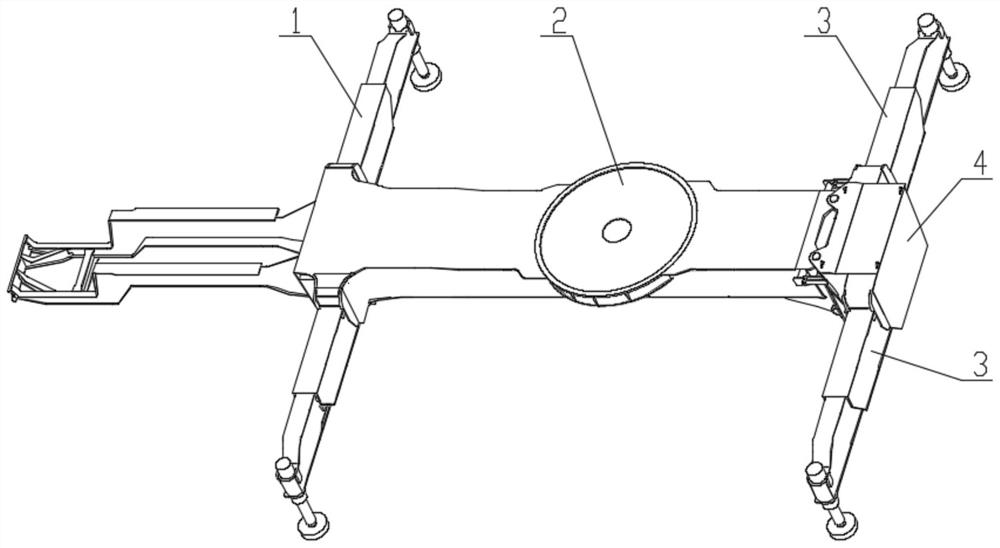
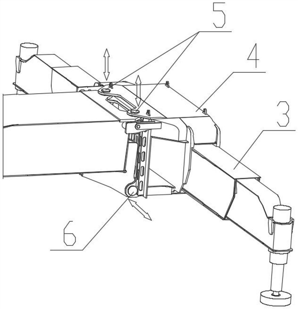
[0043]A vehicle frame structure, comprising a vehicle body 17 and a detachable part 4, the detachable part 4 is located in the longitudinal direction of the vehicle body 17; , hydraulic valves, etc.; the detachable part is connected to the vehicle body through pin shafts, and the pin shafts include two groups, namely the upper pin shaft group 5 and the lower pin shaft group 6; Direction setting, the lower pin group 6 is set along the vertical direction of the vehicle, such as figure 2 shown.

[0044] Described vehicle body 17 comprises vehicle frame 2, and described vehicle frame 2 is positioned at the longitudinal length direction of vehicle body 17; It acts as a supporting force; the movable legs include a front movable leg 1 and a rear movable leg 3; the front movable leg 1 and the rear movable leg 3 are located on both sides of the vehicle frame 2; Under the action of the oil cylinder, it can move telescopically along the fixed box in the frame 2, and its retracted and ...

Embodiment 2

[0059] A mobile crane includes the vehicle frame structure described in Embodiment 1. The vehicle frame structure can be disassembled into at least two parts in the longitudinal direction of the vehicle. In particular, the disassembled part contains the movable outrigger box type. The patented technology also relates to the connection structure of the disassembled part.

[0060] Acronyms and key term definitions:

[0061] Frame: The structural component of the crane, which is the installation carrier of the power system, driving system and other assembly devices, and at the same time plays a supporting role in the operation of the crane.

[0062] Movable Outrigger: A box-shaped structure that can be retracted back and forth to support a crane.

[0063] Fixed outriggers: Belonging to a part of the frame, it is a hollow box-shaped structure, and the movable outriggers can be telescopically moved in the hollow box.

[0064] Vehicle body: the concept of the vehicle body struct...


PUM


Abstract

The invention belongs to the field of engineering machinery, and particularly relates to a frame structure and a mobile crane. The frame structure comprises a vehicle body and a detachable part, wherein the detachable part is positioned in the longitudinal length direction of the vehicle body; the detachable part comprises a part of the vehicle body behind a vehicle and movable support legs; the detachable part is connected with the vehicle body through pin shafts, and the pin shafts comprise an upper pin shaft group and a lower pin shaft group; the upper pin shaft group is arranged in the transverse direction of the vehicle, and the lower pin shaft group is arranged in the vertical direction of the vehicle; the movable support legs comprise front movable support legs and rear movable support legs; and the vehicle body comprises a frame, and the front movable support legs and the rear movable support legs are positioned on two sides of the frame. According to the technical scheme, disassembly and assembly efficiency is improved, and use time of users is shortened.

Description

technical field [0001] The invention belongs to the field of engineering machinery, and in particular relates to a vehicle frame structure and a mobile crane. Background technique [0002] Mobile cranes have the ability to move from one place to another by themselves, and are road machinery that can normally drive on the road. Accordingly, mobile cranes must comply with the legal requirements of traffic regulations, especially with regard to maximum axle load, maximum weight, permitted vehicle dimensions. Large-tonnage cranes generally have a large overall weight. When carrying all components, the overall weight is mostly greater than 55 tons, and the single-axle bridge load is greater than 12 tons, which generally exceeds the allowable range of road regulations. In order to meet regulatory requirements, some components must be disassembled and transported to the point of use. For example, some vehicles need to remove the movable outriggers, transport them to the construct...

Claims


Application Information

Patent Timeline
Patent Type & Authority Applications(China)
IPC IPC(8): B66C23/36B66C23/80
CPCB66C23/36B66C23/80
Inventor 计海兵曹光光蒋静贾晓杰季广科陈江伟
Owner XUZHOU HEAVY MASCH CO LTD
Why Eureka
Eureka Blog
Learn More