
Novel sludge concentration tank

A sludge thickening tank and thickening tank technology, applied in the direction of dewatering/drying/concentrating sludge treatment, can solve problems such as inability to adjust, fix, and sludge moisture content, to avoid water leakage, reduce pollution, and facilitate cleaning. Effect

Pending Publication Date: 2020-11-06
山东万和环保节能技术有限公司
View PDF0 Cites 3 Cited by
  • Summary
  • Abstract
  • Description
  • Claims
  • Application Information

AI Technical Summary

Problems solved by technology

[0003] When the sludge thickening tank of the prior art is used for sedimentation treatment of sludge, the drainage height cannot be adjusted according to the sedimentation depth of the sludge, and the drainage height is fixed. When there is a large amount of sludge, it may cause Part of the sludge is discharged together, and when the amount of sludge is small, more water may not be discharged, and the water content in the sludge is relatively high

Method used


Image

  • Novel sludge concentration tank
  • Novel sludge concentration tank
  • Novel sludge concentration tank

Examples


Embodiment Construction

[0026] In order to make the technical means, creative features, goals and effects achieved by the present invention easy to understand, the present invention will be further described below in conjunction with specific embodiments.

[0027] In describing the present invention, it should be understood that the terms "upper", "lower", "front", "rear", "left", "right", "top", "bottom", "inner", " The orientation or positional relationship indicated by "outside", etc. is based on the orientation or positional relationship shown in the drawings, and is only for the convenience of describing the present invention and simplifying the description, rather than indicating or implying that the referred device or element must have a specific orientation, so as to Specific orientation configurations and operations, therefore, are not to be construed as limitations on the invention.

[0028] In the description of the present invention, it should be noted that, unless otherwise specified and...


PUM


Abstract

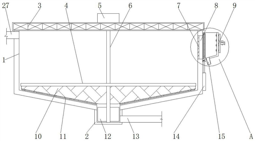
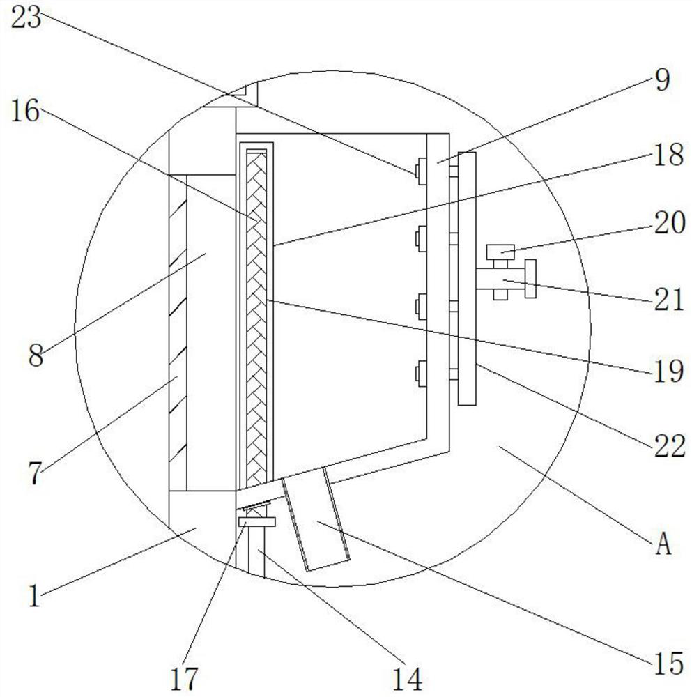
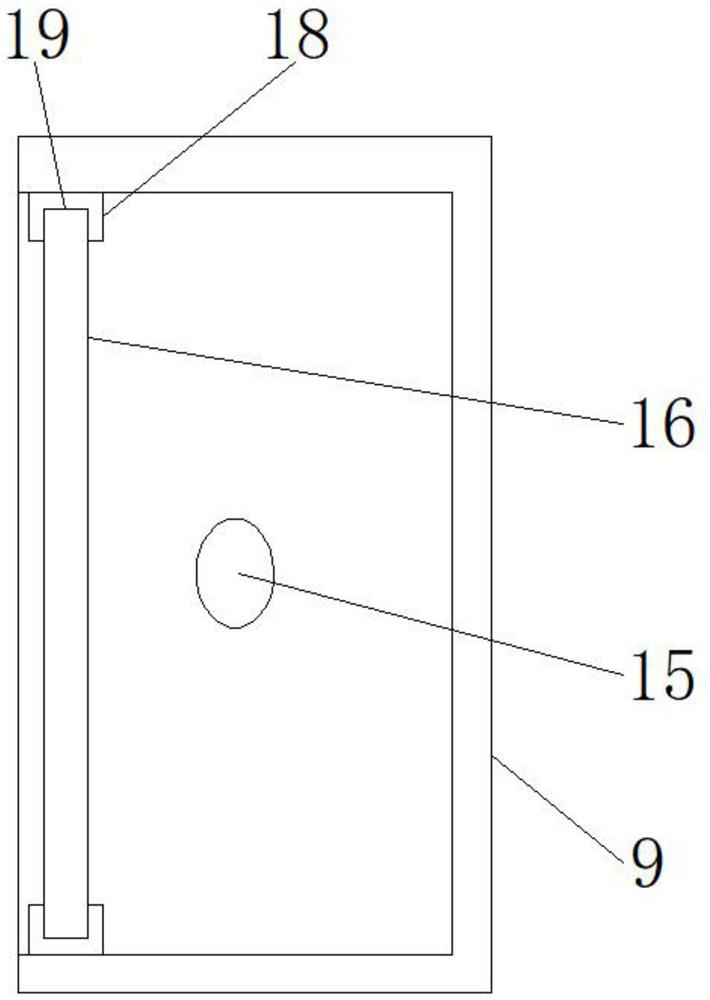
The invention relates to the technical field of sludge concentration. The invention discloses a novel sludge concentration tank comprising a concentration tank and a sludge discharge groove, the sludge discharge groove is connected to the middle of the lower portion of the concentration tank and communicates with the interior of the concentration tank, a drainage mechanism and a sedimentation mechanism are arranged inside and outside the concentration tank, and the drainage mechanism comprises a through opening, a drainage groove, an electric-hydraulic push rod, a drainage pipe, a baffle, an abutting block, a clamping block and a sliding groove; the drainage groove is formed in the surface of the outer wall above the right side of the concentration tank, and the through hole is formed in apart, on the left side of the drainage groove, of the outer wall of the concentration tank. The drainage groove is formed in the outer surface of the upper right side of the concentration tank and communicates with the interior of the concentration tank; the baffle is vertically and slidably fixed in the sliding groove formed in the drainage groove, when the electric-hydraulic push rod pushes thebaffle to move up and down, the height above the baffle can be adjusted, the drainage height can be adjusted according to different amounts of sludge, and the situation that the sludge is dischargedor the water content of the sludge is large is avoided.

Description

technical field [0001] The invention relates to the technical field of sludge concentration, in particular to a novel sludge concentration tank. Background technique [0002] Currently, sludge thickening tanks are used for sludge thickening structures. Generally, it adopts the shape of vertical flow or radial flow. It can be divided into intermittent operation and continuous operation. The former is mainly used in small sewage treatment plants or sewage treatment plants of industrial enterprises, while the latter is used in large and medium-sized sewage treatment plants. The form of the continuous gravity thickening tank is the same as that of the radial flow sedimentation tank, which can be divided into three types: those with mud scraper and sludge stirring device, those without mud scraper, and multi-layer thickeners (with mud scraper). [0003] When the sludge thickening tank of the prior art is used for sedimentation treatment of sludge, the drainage height cannot be ...

Claims


Application Information

Patent Timeline
Patent Type & Authority Applications(China)
IPC IPC(8): C02F11/12
CPCC02F11/12
Inventor 刘永家
Owner 山东万和环保节能技术有限公司
Learn More