
Self-adaptive road surface deceleration strip

A speed bump and self-adaptive technology, applied to roads, roads, road signs, etc., can solve the problems that vehicles are not treated humanely, affect the ride comfort of vehicles, and the fixed form is not reliable

Inactive Publication Date: 2020-11-06
ZHEJIANG AGRI BUSINESS COLLEGE
View PDF0 Cites 2 Cited by
  • Summary
  • Abstract
  • Description
  • Claims
  • Application Information

AI Technical Summary

Problems solved by technology

The first problem is that redundant reminders are issued to speed limit and law-abiding vehicles, which make the vehicles pass through bumps, which affects the ride comfort of the vehicles. Vehicles that obey the traffic rules have not been treated humanely; The production is still made of cast iron, and it must be fixed to the road surface with spikes. During use, the speed bump is subjected to frequent impacts from the wheels. Obviously, this kind of fixing is not reliable, and the speed bump will loosen in a short time. ; The third problem is that the service life of the speed bump made of modified rubber is really limited, which increases the cost of maintenance and replacement
In short, the use effect and maintenance process of the simple speed bumps are not ideal, and the bump reminders for illegal speeding vehicles are not strong enough

Method used


Image

  • Self-adaptive road surface deceleration strip
  • Self-adaptive road surface deceleration strip
  • Self-adaptive road surface deceleration strip

Examples


Embodiment Construction

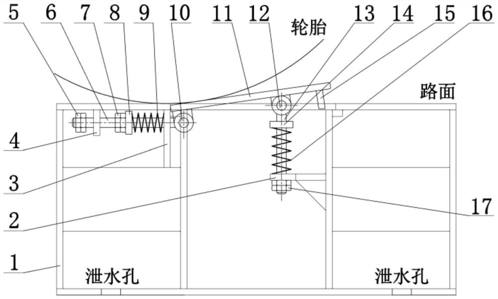
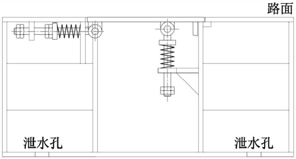
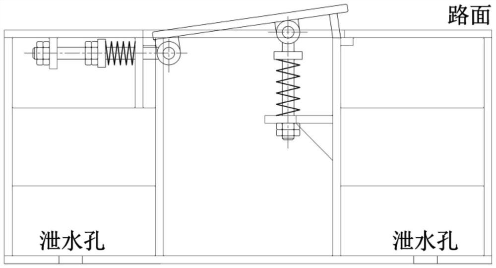
[0021] refer to Figure 1 to Figure 3 The embodiment of an adaptive road speed bump of the present invention will be further described.

[0022] An adaptive road surface deceleration belt 11, including a base 1 located under the road surface and a deceleration belt 11 located at the opening of the road surface, one end of the deceleration belt 11 is hinged with a horizontal limit shaft 6 through a horizontal limit hinge 10, and the other end There is a ratchet iron 15, the base 1 is provided with a horizontal guide plate 3 and a horizontal limit plate 4, one end of the horizontal limit shaft 6 is slidably connected to the horizontal guide plate 3, and the other end is slidably connected to the horizontal On the limiting plate 4, a horizontal spring retaining ring 8 is arranged between the corresponding horizontal guide plate 3 and the horizontal limiting plate 4 on the horizontal limiting shaft 6, and the corresponding horizontal spring retaining ring 8 and A horizontal sprin...


PUM


Abstract

The invention provides a self-adaptive road surface deceleration strip. The self-adaptive road surface deceleration strip comprises a base located below a road surface and a deceleration strip locatedat an opening of the road surface, wherein a horizontal limiting shaft is hinged to one end of the deceleration strip, the other end is provided with pawl iron, a horizontal guide plate and a horizontal limiting plate are arranged on the base, one end of the horizontal limiting shaft is slidably connected to the horizontal guide plate, the other end is slidably connected to the horizontal limiting plate, a horizontal spring check ring is arranged on the horizontal limiting shaft, a horizontal spring is arranged on the horizontal limiting shaft, a horizontal limiting locking nut is arranged onthe horizontal limiting shaft, a vertical limiting shaft is hinged to the middle of the deceleration strip, a vertical direction limiting plate is arranged on the base, a horizontal oblong hole is formed in the vertical direction limiting plate, and the vertical limiting shaft is inserted into the horizontal oblong hole, a vertical spring check ring is arranged in the middle of the vertical limiting shaft, a vertical spring is arranged on the vertical limiting shaft, and a vertical limiting locking nut is arranged at the end, which is away from the deceleration strip, of the vertical limitingshaft. The self-adaptive road surface deceleration strip provided by the invention is good in adaption effect.

Description

technical field [0001] The invention relates to the technical field of urban construction, in particular to an adaptive road speed bump. Background technique [0002] There are many pedestrians passing by in the entrance areas of schools, hospitals, and residential areas. In order to ensure traffic safety, speed bumps are often set up on the corresponding roads in those areas to remind vehicles to pass at a speed limit. The simple speed bumps currently installed have almost the same appearance, fixing form and use effect, and the existing problems are basically the same. The first problem is that redundant reminders are issued to speed limit and law-abiding vehicles, which make the vehicles pass through bumps, which affects the ride comfort of the vehicles. Vehicles that obey the traffic rules have not been treated humanely; The production is still made of cast iron, and it must be fixed to the road surface with spikes. During use, the speed bump is subjected to frequent im...

Claims


Application Information

Patent Timeline
IPC IPC(8): E01F9/529
CPCE01F9/529
Inventor 付君伟
Owner ZHEJIANG AGRI BUSINESS COLLEGE
Learn More