Steam turbine steam snow sweeper

A technology for snow removal vehicles and steam turbines, applied in the field of steam turbines, can solve the problems of no energy recovery and utilization, influence of vehicle driving, consumption of energy carried by the vehicle body, etc.

Inactive Publication Date: 2020-11-06
DONGYANG NARUI STEAM ENGINE EQUIP TECH CO LTD
View PDF0 Cites 1 Cited by
  • Summary
  • Abstract
  • Description
  • Claims
  • Application Information

AI Technical Summary

Problems solved by technology

[0002] At present, the more common snow removal vehicles mostly use snow shovels and other mechanisms to clean and accumulate snow on the road surface, while some snow removal vehicles can collect the removed snow, squeeze and store the ice and snow after collection or melt the ice and snow After forming water, it sprays to the outside world, but most of these snow removal vehicles consume the energy carried by the body when performing snow removal work, and there is no function of energy recovery and utilization during the work process, and the sprayed water will quickly condense into ice on the road surface. impact on vehicle movement

Method used


Image

  • Steam turbine steam snow sweeper
  • Steam turbine steam snow sweeper
  • Steam turbine steam snow sweeper

Examples


Embodiment Construction

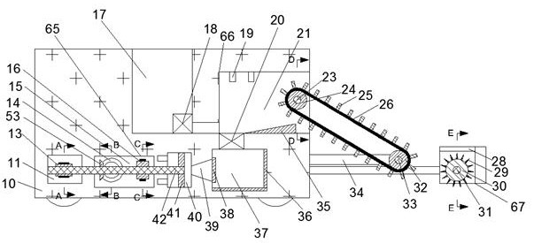
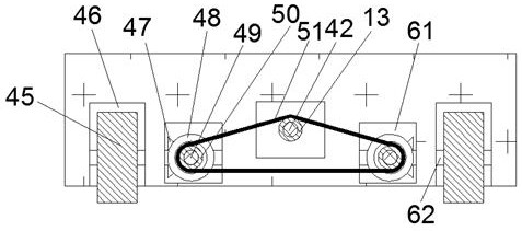
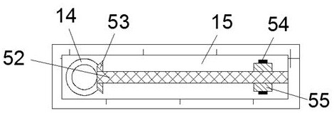
[0017] Combine below Figure 1-6 The present invention is described in detail, for the convenience of description, the orientations mentioned below are now specified as follows: figure 1 The projection relationship of itself is the same as the up, down, left, right, front, and rear directions.

[0018] refer to Figure 1-6 , according to an embodiment of the present invention, a steam turbine steam snow removal vehicle includes a casing 10, and the casing 10 is provided with a liquid discharge cavity 17 with an open upper end, and a melting cavity 21 is provided in the right end wall of the liquid discharge cavity 17 , the lower end wall of the melting chamber 21 is provided with a heating cavity 37, the left end wall of the heating cavity 37 is provided with a rotating cavity 40, the left end wall of the rotating cavity 40 is provided with an intermediate cavity 15, and the left end wall of the intermediate cavity 15 is provided There is a transmission cavity 11 inside, and...


PUM


Abstract

The invention discloses a steam turbine steam snow sweeper comprising a shell. A liquid discharging cavity with an opening in the upper end is formed in the shell. A melting cavity is formed in the right end wall of the liquid discharging cavity; a heating cavity is formed in the lower end wall of the melting cavity; a rotating cavity is formed in the left end wall of the heating cavity; a middlecavity is formed in the left end wall of the rotating cavity; a transmission cavity is formed in the left end wall of the middle cavity; two moving cavities which are symmetrical front and back are formed in the front end wall and the rear end wall of the transmission cavity; a driven cavity is formed in the rear end wall of the melting cavity; the right end, rotationally connected with the left end wall of the transmission cavity, of the driving shaft is located in the rotating cavity; the right end of the driving shaft is fixedly connected with a steam turbine blade; and a conveying plate isarranged in the melting cavity, the conveying belt rotates to drive accumulated snow to enter the melting cavity through the conveying plate, two fixed triangular blocks which are symmetrical front and back are arranged on the right side of the shell, a crushing blade is arranged between the two fixed triangular blocks, and the crushing blade rotates to conduct icebreaking.

Description

technical field [0001] The invention relates to the technical field of steam turbines, in particular to a steam turbine steam snow removal vehicle. Background technique [0002] At present, the more common snow removal vehicles mostly use snow shovels and other mechanisms to clear and accumulate the snow on the road, while some snow removal vehicles can collect the removed snow, and then squeeze the ice and snow for storage or melt the ice and snow after collection. After the water is formed, it is sprayed to the outside world, but these snow removal trucks mostly consume the energy carried by the body when carrying out snow removal work. There is no energy recovery function during the work process, and the sprayed water will quickly condense into ice on the road. The driving of the vehicle is affected. SUMMARY OF THE INVENTION [0003] The purpose of the present invention is to provide a steam turbine steam snow removal vehicle for overcoming the above-mentioned defects ...

Claims


Application Information

Patent Timeline
Patent Type & Authority Applications(China)
IPC IPC(8): E01H5/10E01H5/12F01D15/00
CPCE01H5/106E01H5/12F01D15/00
Inventor 谢毅杰
Owner DONGYANG NARUI STEAM ENGINE EQUIP TECH CO LTD
Why Eureka
Try Eureka