Real-time pressure detection supporting device for slag treatment roller

A technology of real-time pressure and support device, applied in the direction of measuring device, measuring force, instrument, etc., can solve the problems of wear of supporting wheel shell, thrust wheel shell and supporting ring, axle impact fracture, unobservable development process, etc. Equipment installation, optimizing equipment design, and achieving predictive maintenance effects

Pending Publication Date: 2020-11-06
SHANGHAI BAOSTEEL ENERGY TECH
View PDF0 Cites 0 Cited by
  • Summary
  • Abstract
  • Description
  • Claims
  • Application Information

AI Technical Summary

Problems solved by technology

[0003] When installing the traditional roller support device, the machined wheel set reference block is used to measure and position first, and then the roller body is installed on the support device. Due to the heavy cylinder body, the support device has a certain deformation, which will cause the cylinder body The axis is not parallel to the axis of the wheel train of the supporting device. Generally, the state of the cylinder axis of the drum is judged by the lead pressing method. This method is difficult to analyze and adjust. Therefore, manual inspection can only be relied on during production and operation. During slag, there are occasional slag splashes between the support wheel and the support ring, and abnormal conditions such as long-term unilateral force on the thrust wheel, resulting in accelerated wear of the support wheel shell, thrust wheel shell and support ring, and even impact fracture of the axle
The formation and development process of wheel shaft fatigue cracks cannot be observed during production. Once wheel shaft fatigue fracture occurs, it will cause huge production losses and cause serious damage

Method used


Image

  • Real-time pressure detection supporting device for slag treatment roller
  • Real-time pressure detection supporting device for slag treatment roller
  • Real-time pressure detection supporting device for slag treatment roller

Examples


Embodiment Construction

[0033] The following will combine Figure 1 to Figure 5 A detailed description of a real-time pressure detection support device for a slag treatment drum provided by the present invention is given. The scope of protection is not limited to the following embodiments, and those skilled in the art can modify and embellish it within the scope of not changing the spirit and content of the present invention.

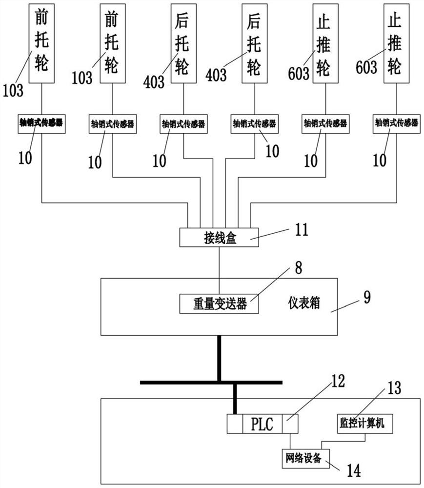
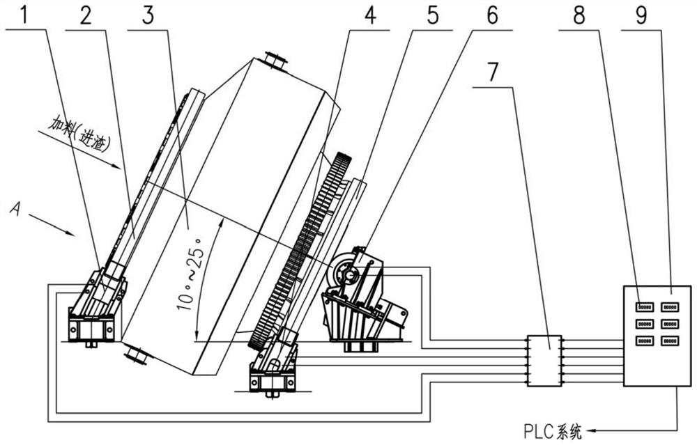
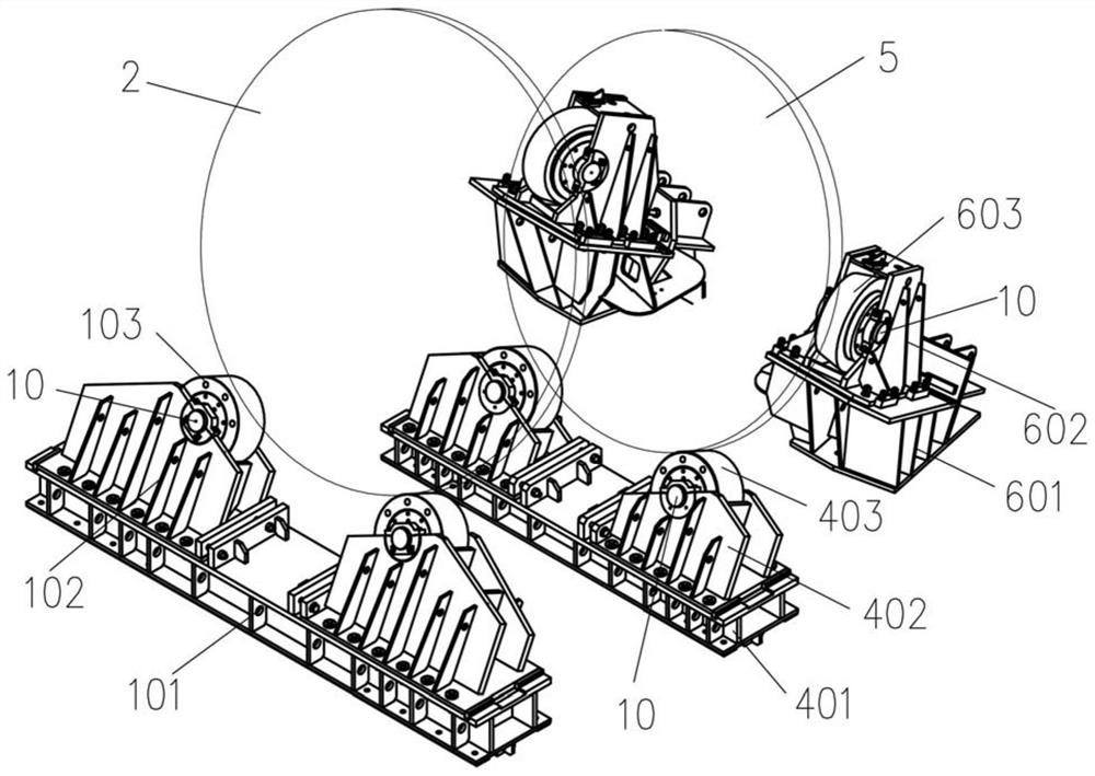
[0034] Please refer to Figure 1 to Figure 5 , a support device for real-time pressure detection of a slag processing drum, comprising a force-measuring front supporting wheel device 1, a force-measuring rear supporting wheel device 4, a force-measuring thrust wheel device 6 and a weight transmitter 8, the force-measuring front supporting wheel The axles of device 1, the force-measuring rear supporting wheel device 4 and the force-measuring thrust wheel device 6 all adopt pivot pin sensors 10, and the pin pin sensors 10 are electrically connected with the weight transmitter 8...


PUM


Abstract

The invention relates to a real-time pressure detection supporting device for a slag treatment roller. The device comprises a force-measuring front riding wheel device, a force-measuring rear riding wheel device, a force-measuring thrust wheel device and a weight transmitter, wherein the wheel shafts of the force-measuring front riding wheel device, the force-measuring rear riding wheel device andthe force-measuring thrust wheel device all adopt shaft pin type sensors, and the shaft pin type sensors are electrically connected with the weight transmitter. According to the invention, online detection and diagnosis of the supporting device of the slag treatment roller are realized, the installation, operation and health states of the roller are judged, optimization and adjustment of equipment are facilitated, and accurate maintenance and predictive maintenance of the equipment state are realized.

Description

technical field [0001] The invention relates to the technical field of slag treatment by a drum method, in particular to a real-time pressure detection support device for a slag processing drum. Background technique [0002] The existing slag treatment drum supporting device is composed of a traditional front supporting roller device, a rear supporting roller device and a thrust wheel device, wherein the front supporting roller device and the rear supporting roller device are both composed of a pair of supporting rollers and a large base , each pair of supporting rollers respectively supports the corresponding support ring, which not only allows the drum body to rotate, but also transmits load to the foundation. The thrust wheel device consists of two independent thrust wheel sets and their bases. The thrust wheel sets are supported on the rear support ring to limit or control the axial movement of the drum body. [0003] When installing the traditional roller support devic...

Claims


Application Information

Patent Timeline
IPC IPC(8): G01L1/22G01L1/26
CPCG01L1/2206G01L1/2256G01L1/2262G01L1/26
Inventor 吴俊龙刘帅陈诚张敏滨
Owner SHANGHAI BAOSTEEL ENERGY TECH
Why Eureka
Try Eureka