Fault diagnosis system and method for high-power permanent magnet motor

A fault diagnosis system and permanent magnet motor technology, applied in the direction of motor generator testing, etc., can solve the problems of inaccurate diagnosis, inability to detect motor loss of field faults, and high cost, so as to improve system reliability, achieve predictive maintenance, and effectively The effect of fault diagnosis

Active Publication Date: 2020-07-31
SHANDONG UNIV OF SCI & TECH
View PDF11 Cites 0 Cited by
  • Summary
  • Abstract
  • Description
  • Claims
  • Application Information

AI Technical Summary

Problems solved by technology

Because the high-power permanent magnet motor (3000KW, 90r / min) is large in size (2m in diameter), heavy in weight (20t), and high in cost, it is mainly used to drive key equipment. Once it fails and stops unexpectedly, it will have a great impact on production, etc.
[0003] However, the traditional motor fault diagnosis methods mainly use the multi-point embedded thermal resistance temperature measurement method to detect the motor over-temperature fault, which cannot realize the full-coverage detection of the motor winding temperature; use the current amplitude comparison to judge the over-current and short-circuit faults, and cannot detect the motor. Demagnetization faults are detected, and a single detection method cannot achieve effective fusion of information, resulting in inability to diagnose faults or inaccurate diagnosis

Method used


Image

  • Fault diagnosis system and method for high-power permanent magnet motor
  • Fault diagnosis system and method for high-power permanent magnet motor
  • Fault diagnosis system and method for high-power permanent magnet motor

Examples


Embodiment 1

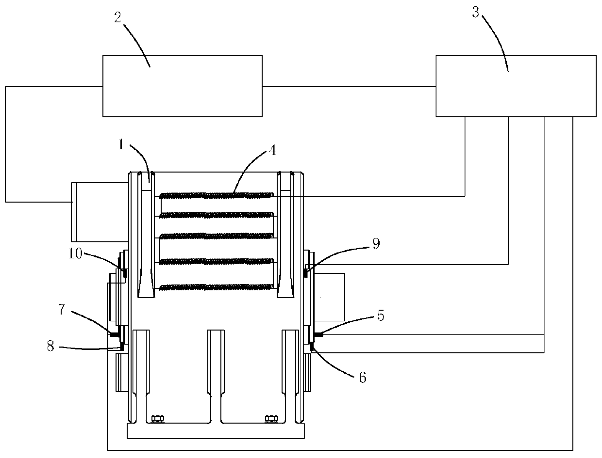
[0036] to combine figure 1 , a high-power permanent magnet motor fault diagnosis system, including a permanent magnet motor 1, a servo controller 2 and an industrial control computer 3.

[0037] The permanent magnet motor 1 is connected with the servo controller 2, and the servo controller 2 is electrically connected with the industrial control computer 3. The permanent magnet motor 1 is provided with a vibration sensor and a temperature sensor, and both the vibration sensor and the temperature sensor are connected with the industrial control computer. The magneto is also connected with the industrial control computer 3 through the temperature measuring optical fiber 4 .

[0038] The servo controller 2 collects the current signal of the permanent magnet motor 1, and uploads the current signal to the industrial control computer, and the industrial control computer 3 controls the permanent magnet motor 1 to stop through the servo controller.

[0039] The industrial control comp...

Embodiment 2

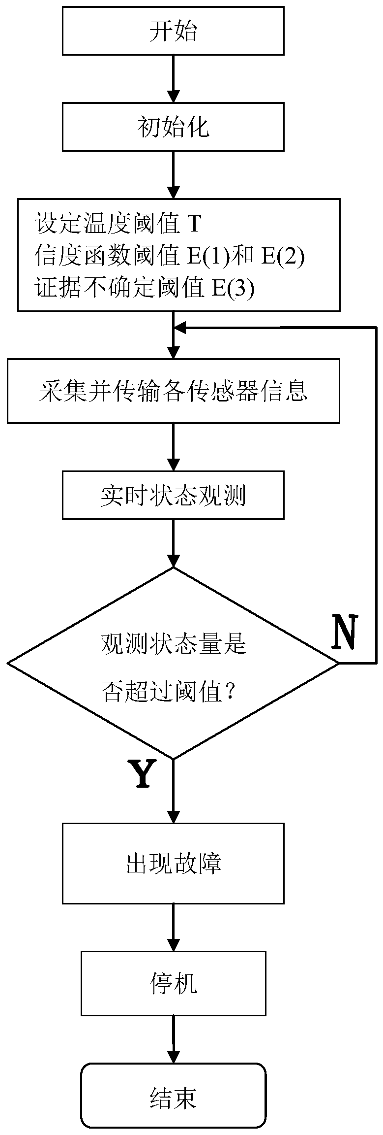
[0049] The diagnosis method of a kind of high-power permanent magnet motor fault diagnosis system described in the above-mentioned embodiment comprises the following steps:

[0050] Step 1: According to the status and monitoring requirements of the actual high-power permanent magnet motor, a motor temperature rise model is established for motor over-temperature faults, and a multi-source sensor fusion fault diagnosis model based on D-S theory is established for motor bearing faults and motor demagnetization faults;

[0051] Motor temperature rise model: Since the temperature of different positions of the stator winding of the permanent magnet motor is different, in order to realize distributed comprehensive detection, the center of the permanent magnet motor shaft is used as the origin to establish a three-dimensional coordinate system of the motor, and the temperature of the stator winding of the motor is divided into grids. Perform coordinate simulation calculation output to ...


PUM


Abstract

The present invention provides a large-power permanent magnet motor fault diagnosis system and method. The system comprises a permanent magnet motor, a servo controller and an industrial control computer. The permanent magnet motor is connected with the servo controller, the servo controller is electrically connected with the industrial control computer, the permanent magnet motor is provided witha vibration sensor and a temperature sensor, the vibration sensor and the temperature sensor are connected with the industrial control computer, and the permanent magnet motor is connected with the industrial control computer through a temperature measurement optical fiber. The present invention creatively provides a mixed intelligent fault diagnosis method with a three-in-one mode of all-opticalwinding temperature detection, motor bearing vibration detection and permanent magnet motor current analysis. The large-power permanent magnet motor fault diagnosis system and method can discover thefaults of the large-scale permanent magnet motor easier, can reduce the maintenance, can improve the system reliability, can achieve foreseeability maintenance and can solve the problem that a large-scale permanent magnet motor cannot perform advance, comprehensive and effective fault diagnosis.

Description

technical field [0001] The invention relates to the field of fault diagnosis of high-power permanent magnet motors, in particular to a fault diagnosis system and method for high-power permanent magnet motors. Background technique [0002] With the improvement of the performance of rare earth permanent magnet materials in recent years, the design of large permanent magnet motors and the continuous development of drive control technology, high-power variable frequency speed regulation low-speed permanent magnet motors are characterized by high efficiency and energy saving, large starting torque, and stepless speed regulation. Advantages, it is more and more widely used in industrial occasions, and is gradually replacing the original traditional drive method of asynchronous motor + reducer. Because the high-power permanent magnet motor (3000KW, 90r / min) is large in size (2m in diameter), heavy in weight (20t), and high in cost, it is mainly used to drive key equipment. Once it ...

Claims


Application Information

Patent Timeline
Patent Type & Authority Patents(China)
IPC IPC(8): G01R31/34
CPCG01R31/34
Inventor 岳彦博王永震战克华
Owner SHANDONG UNIV OF SCI & TECH
Why Eureka
Try Eureka