
Soil sampling device for highway engineering

A soil sampling and engineering technology, applied in the direction of sampling devices, etc., can solve the problems of soil layer damage, difficult to take out, difficult to penetrate deep into the soil, etc., and achieve the effect of high efficiency and reasonable structure.

Inactive Publication Date: 2020-11-06
刘鸿
View PDF0 Cites 5 Cited by
  • Summary
  • Abstract
  • Description
  • Claims
  • Application Information

AI Technical Summary

Problems solved by technology

[0004] The purpose of the present invention is to solve the existing problems in the prior art that the soil sampling equipment is not easy to penetrate into the deep soil layer, and it is not convenient to sample the soil at different depths, and the soil enters the hollow long rod, which is difficult to take out, and the soil layer is easily damaged when the soil is taken out. Shortcomings, and proposed a soil sampling device for highway engineering

Method used


Image

  • Soil sampling device for highway engineering
  • Soil sampling device for highway engineering
  • Soil sampling device for highway engineering

Examples


Embodiment 1

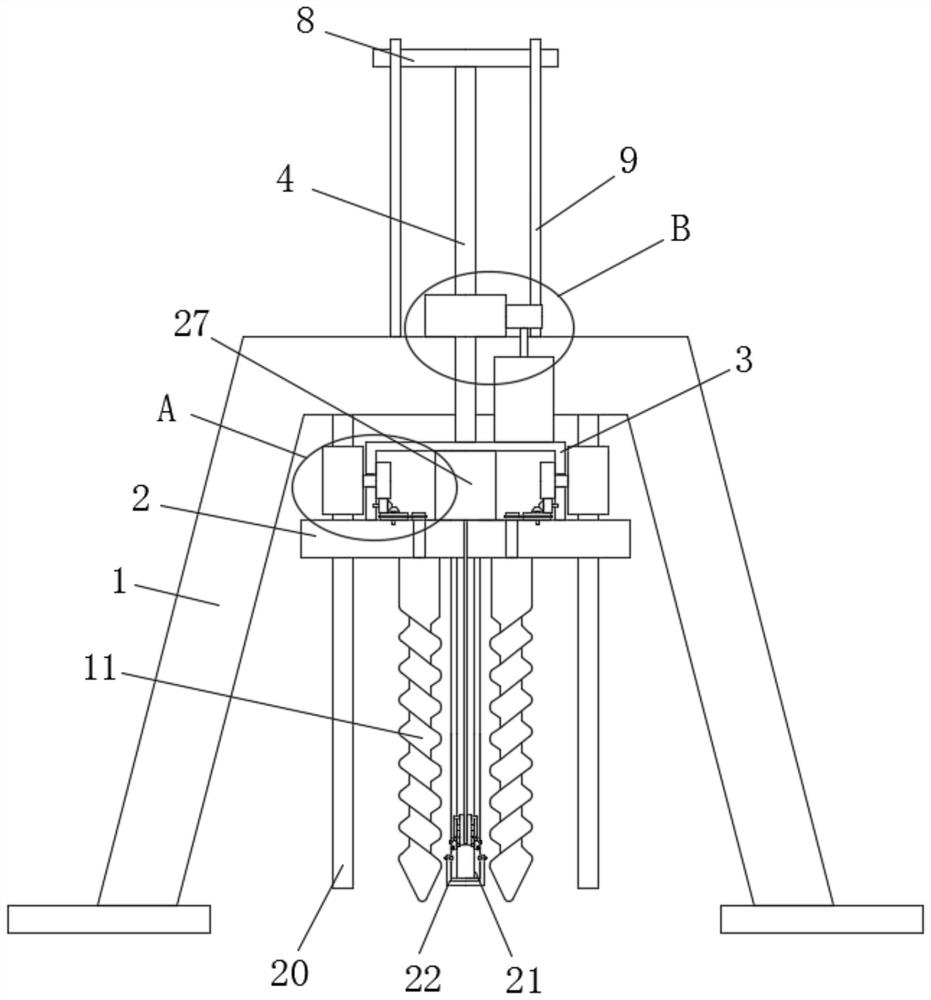
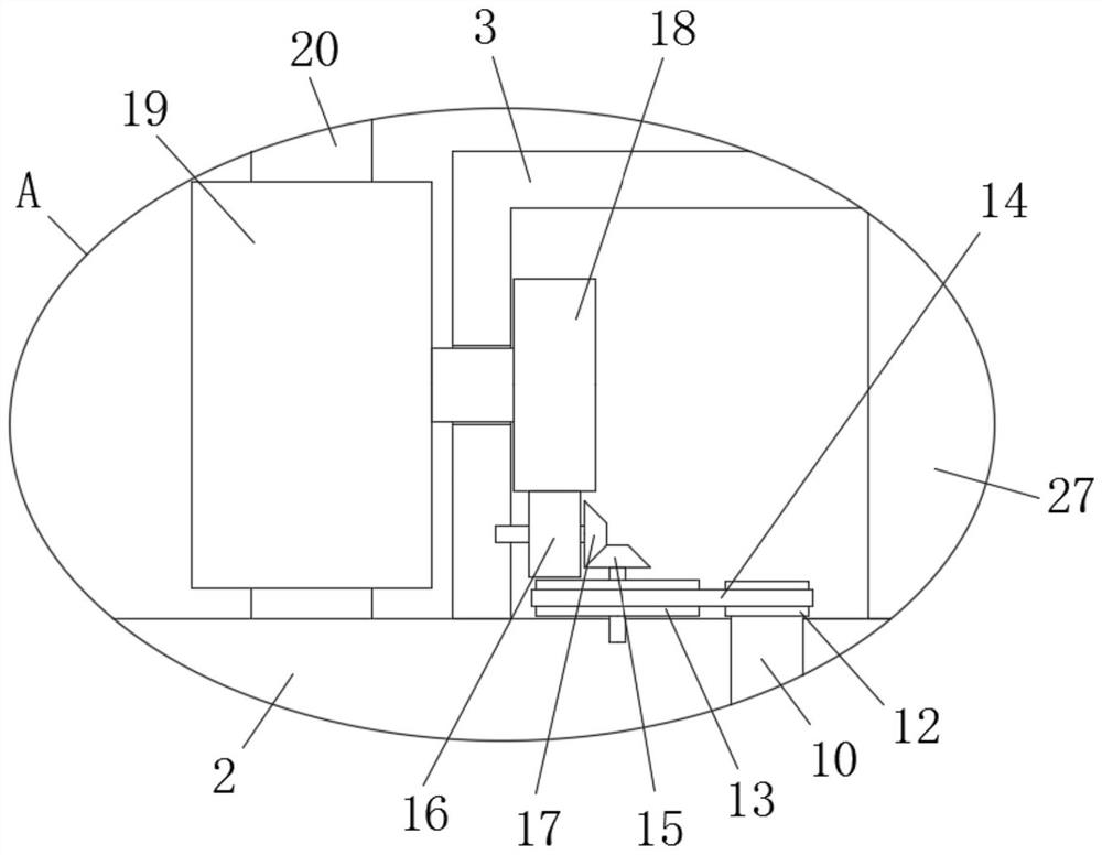
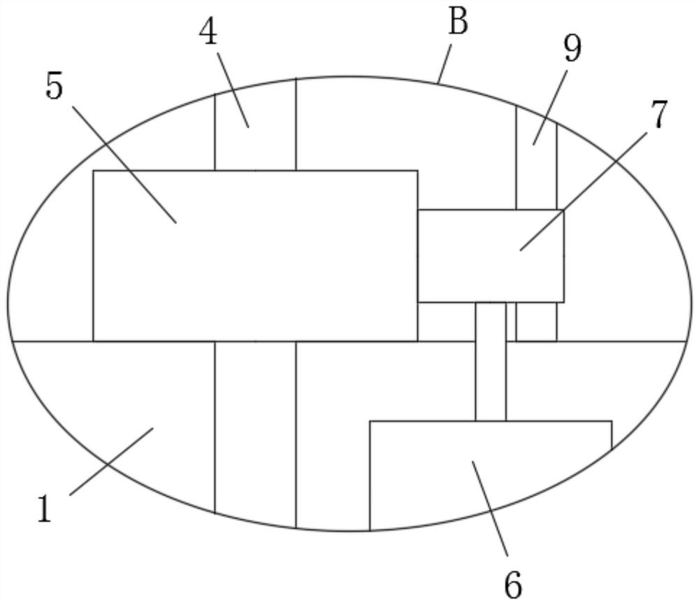
[0026] refer to Figure 1-7, a soil sampling device for highway engineering, comprising a sampling frame 1, the sampling frame 1 is provided with a moving plate 2, the top of the moving plate 2 is fixedly equipped with a control box 3, and the top of the control box 3 is fixedly connected with a first screw rod 4, The top of the sampling rack 1 is provided with a sliding hole, the first screw rod 4 is slidably connected in the sliding hole, the first screw rod 4 is threadedly connected with the first control wheel 5, and the first control wheel 5 is rotatably mounted on the top of the sampling rack 1. The first motor 6 is fixedly installed on the frame 1, the output shaft of the first motor 6 is fixedly connected with the second control wheel 7, the second control wheel 7 is engaged with the first control wheel 5, and the top of the moving plate 2 is provided with two Rotation hole, in two rotation holes, all rotation is installed with rotation bar 10, and the bottom end of tw...

Embodiment 2

[0032] refer to Figure 1-7 , a soil sampling device for highway engineering, comprising a sampling rack 1, the sampling rack 1 is provided with a moving plate 2, the top of the moving plate 2 is fixedly installed with a control box 3 by screws, and the top of the control box 3 is fixedly connected with a second A screw 4, the top of the sampling rack 1 is provided with a sliding hole, the first screw 4 is slidably connected in the sliding hole, the first screw 4 is threaded with a first control wheel 5, and the first control wheel 5 is rotatably mounted on the sampling rack 1 On the top of the sampling frame 1, a first motor 6 is fixedly installed by screws, and the output shaft of the first motor 6 is fixedly connected with a second control wheel 7 by screws, and the second control wheel 7 meshes with the first control wheel 5 to move The top of the plate 2 is provided with two rotating holes, and a rotating rod 10 is installed in the two rotating holes, and the bottom ends ...


PUM


Abstract

The invention belongs to the field of highway engineering, and particularly relates to a soil sampling device for highway engineering. In the prior art, the existing soil sampling equipment is not easy to go deep into the deep layer of soil, soil at different depths is inconvenient to sample, the soil enters the hollow long rod and is difficult to take out, and the soil layer damage is easily caused when soil is taken out. A purpose of the invention is to solve the problems in the prior art. According to the technical scheme of the invention, the soil sampling device comprises a sampling frame, which is provided with a movable plate, wherein a control box is fixedly mounted at the top of the movable plate, a first screw rod is fixedly connected to the top of the control box, a sliding holeis formed in the top of the sampling frame, and the first screw rod is slidably connected into the sliding hole. According to the invention, the soil sampling device is reasonable in structure, and can go deep into the deep layer of soil so as to conveniently sample soil at different depths, the soil can be tunneled when the depth is adjusted, the sampling pipe can conveniently enter the samplingpipe for sampling, the soil cannot be blocked in the sampling pipe, the taken-out soil cannot be damaged, and the sampling efficiency is high.

Description

technical field [0001] The invention relates to the technical field of road engineering, in particular to a soil sampling device for road engineering. Background technique [0002] Highway engineering refers to the survey, measurement, design, construction, maintenance, management, etc. of highway structures. Highway engineering structures include roadbeds, pavements, bridges, culverts, tunnels, drainage systems, safety protection facilities, greening and traffic monitoring facilities, and Houses, workshops and other service facilities used for construction, maintenance and monitoring. The task of new construction or reconstruction of roads is determined according to the planning of the road network. The construction of roads in a country should be considered comprehensively in combination with transportation such as railways, waterways, and aviation. According to its political, military, economic, and people's life needs, combined with geographical and environmental conditi...

Claims


Application Information

Patent Timeline
IPC IPC(8): G01N1/08
CPCG01N1/08
Inventor 刘鸿
Owner 刘鸿
Learn More