Large dynamic signal demodulation model device based on phase modulation

A phase modulation and model device technology, applied in the field of microwave photonics, can solve the problems of limiting the wide application of microwave optical links, many bias point controls, and increasing complexity, and achieves improved dynamic range, adjustable filter bandwidth, and realization of Precisely controlled effects

Active Publication Date: 2020-11-06
THE 44TH INST OF CHINA ELECTRONICS TECH GROUP CORP +1
View PDF6 Cites 1 Cited by
  • Summary
  • Abstract
  • Description
  • Claims
  • Application Information

AI Technical Summary

Problems solved by technology

Several methods have their own advantages and disadvantages. The phase-locked loop has a large dynamic range, but its bandwidth is usually less than GHz due to the phase-locked delay; the cascaded optical filter has the advantages of high linearity, large dynamics and large bandwidth, but Its bias point control is more complex in the system, and the dual-wavelength third-order intermodulation cancellation has the characteristics of large dynamic and large bandwidth, but the independent dual light source makes the system more complex in light source control and optical filtering, which seriously limits the phase-based modulation. Wide application of large dynamic microwave optical links

Method used


Image

  • Large dynamic signal demodulation model device based on phase modulation
  • Large dynamic signal demodulation model device based on phase modulation
  • Large dynamic signal demodulation model device based on phase modulation

Examples


Embodiment Construction

[0024] The following will clearly and completely describe the technical solutions in the embodiments of the present invention with reference to the accompanying drawings in the embodiments of the present invention. Obviously, the described embodiments are only some, not all, embodiments of the present invention. Based on the embodiments of the present invention, all other embodiments obtained by persons of ordinary skill in the art without making creative efforts belong to the protection scope of the present invention.

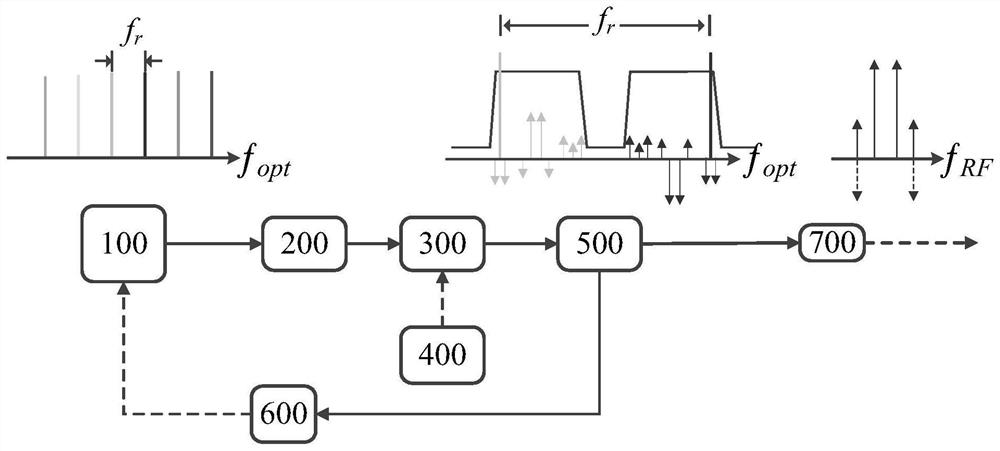
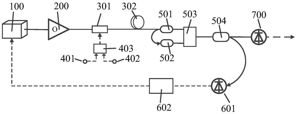
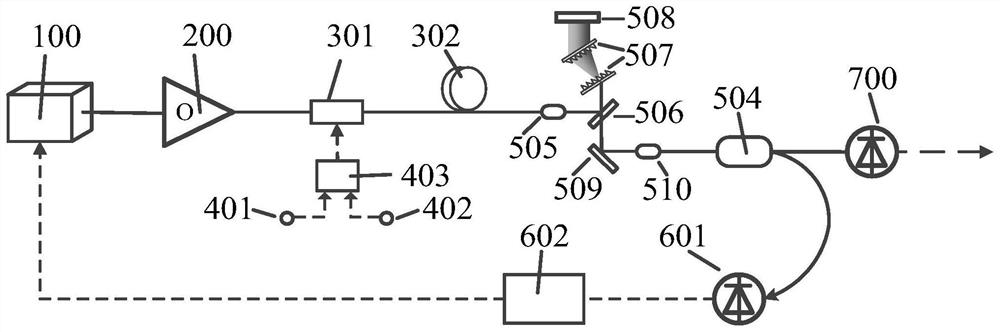
[0025] In the drawings of the embodiments of the present invention, solid lines represent optical paths, and short dashed lines represent circuits. The present invention will be described in detail below in conjunction with specific drawings.

[0026] It should be noted that since the embodiments of the present invention focus on the demodulation of laser signals, the laser in the present invention may exist in the form of optical signals, carrier signals, opti...


PUM


Abstract

The invention belongs to the technical field of microwave photons, and particularly relates to a large dynamic signal demodulation model device based on phase modulation. The demodulation model devicecomprises an optical frequency comb source, an optical amplification module, a phase modulation module, a radio frequency source module, an optical filtering module, a frequency locking control module and a photoelectric detection module. The optical frequency comb source is connected with an optical input port of the phase modulation module after passing through the optical amplification module;meanwhile, a radio frequency signal output by the radio frequency source module is connected with a radio frequency input port of the phase modulation module, and an optical signal output by the phase modulation module is divided into two paths after being processed by the optical filtering module: a first path is connected with the frequency locking control module to generate a feedback signal and output the feedback signal to the optical frequency comb source to control and adjust the absolute comb tooth frequency of the optical frequency comb source; a second path is connected with the photoelectric detection module to generate and output a radio frequency signal; the optical frequency comb source is used for providing phase-locked dual-wavelength laser, accurate adjustment and suppression of high-order spurious signals are achieved, and therefore the third-order intermodulation value and the dynamic range of a link are improved.

Description

technical field [0001] The invention belongs to the field of microwave photon technology, in particular to a large dynamic signal demodulation model device based on phase modulation. Background technique [0002] The transmission characteristics of large dynamic and broadband radio frequency signals are the core requirements of electronic information equipment such as next-generation radar, electronic warfare, and communication. However, using the coaxial cable commonly used for radio frequency signal transmission as the transmission medium has many problems such as large volume, heavy weight, weak anti-electromagnetic interference ability, and large loss. Microwave photonic technology modulates radio frequency signals onto optical carriers, and uses optical fiber as the transmission medium for long-distance transmission; this technology has the following unique advantages: [0003] (1) The optical fiber is small in size, light in weight, and good in flexibility; (2) Strong...

Claims


Application Information

Patent Timeline
Patent Type & Authority Applications(China)
IPC IPC(8): H04B10/2575H04B10/556H04B10/69H04B10/70
CPCH04B10/2575H04B10/5561H04B10/69H04B10/70
Inventor 王超瞿鹏飞孙力军
Owner THE 44TH INST OF CHINA ELECTRONICS TECH GROUP CORP
Why Eureka
Try Eureka