A photocatalytic reduction of co 2 reactor

A technology of CO2 and photocatalysis, applied in chemical instruments and methods, chemical/physical processes, chemical/physical/physicochemical processes, etc., can solve problems such as inapplicability, and achieve the effect of efficient photocatalytic reduction

Active Publication Date: 2021-03-23
HARBIN UNIV
View PDF7 Cites 0 Cited by
  • Summary
  • Abstract
  • Description
  • Claims
  • Application Information

AI Technical Summary

Problems solved by technology

[0002] For example, the publication number CN206730862U is a photocatalytic reduction of CO 2 The reactor has a cylindrical structure as a whole, and includes a hollow cylindrical heating layer, a reflective layer attached to the inner wall of the heating layer, and coaxially extending reaction tubes and light sources installed inside the heating layer. , wherein the reaction tube extends in a spiral shape around the light source, and its first and last ends have material inlets and material outlets respectively, and a photocatalyst is attached to the inner wall, which is used to convert the CO to be reacted 2 The interior of the hollow tube through the reaction tube is kept spirally transported and reacted synchronously; the disadvantage of this utility model is that it cannot be applied to a large amount of CO 2 photocatalytic reduction

Method used


Image

  • A photocatalytic reduction of co  <sub>2</sub> reactor
  • A photocatalytic reduction of co  <sub>2</sub> reactor
  • A photocatalytic reduction of co  <sub>2</sub> reactor

Examples


specific Embodiment approach 1

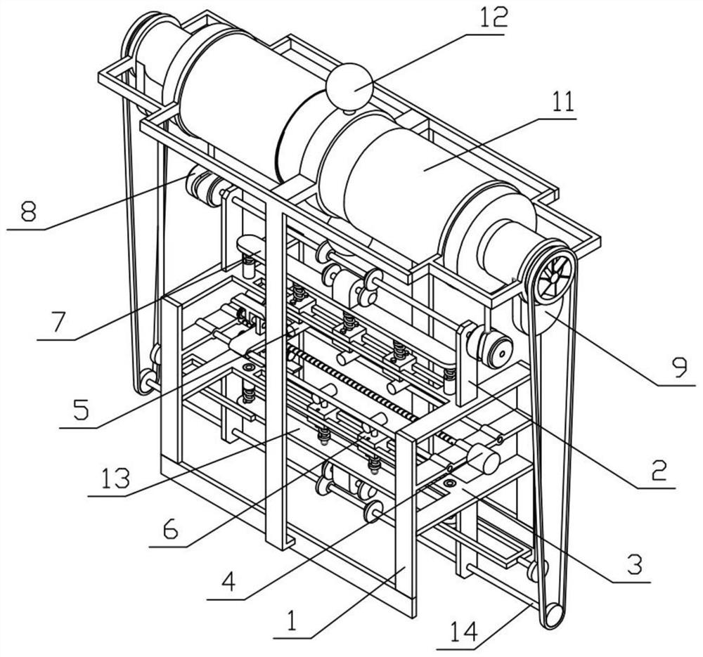
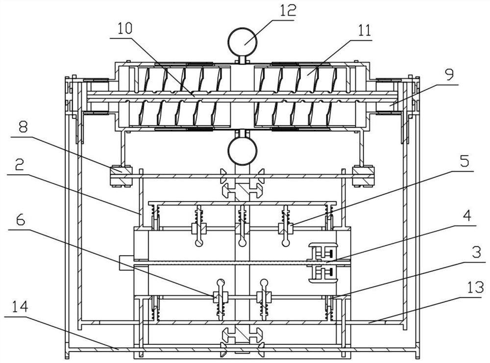
[0040] Combine below Figure 1-16 Describe this embodiment, a photocatalytic reduction of CO 2 Reactor, including device bracket 1, sliding bracket I2, sliding bracket II3, switching mechanism 4, pushing mechanism I5, pushing mechanism II6, pushing bracket I7, reciprocating mechanism 8, ventilation mechanism 9, ultraviolet lamp cover 10, oxidation mechanism I11, Oxidation mechanism II12, pushing bracket II13 and transmission mechanism 14, the device bracket 1 is fixedly connected with sliding bracket I2 and sliding bracket II3, the device bracket 1 is connected with switching mechanism 4, and switching mechanism 4 is located between sliding bracket I2 and sliding bracket II3 Among them, the sliding bracket I2 is connected with a plurality of pushing mechanisms I5, the sliding bracket II3 is connected with a plurality of pushing mechanisms II6, the sliding bracket I2 is slidingly connected with a pushing bracket I7, and the pushing bracket I7 is fixedly connected with the slidi...

specific Embodiment approach 2

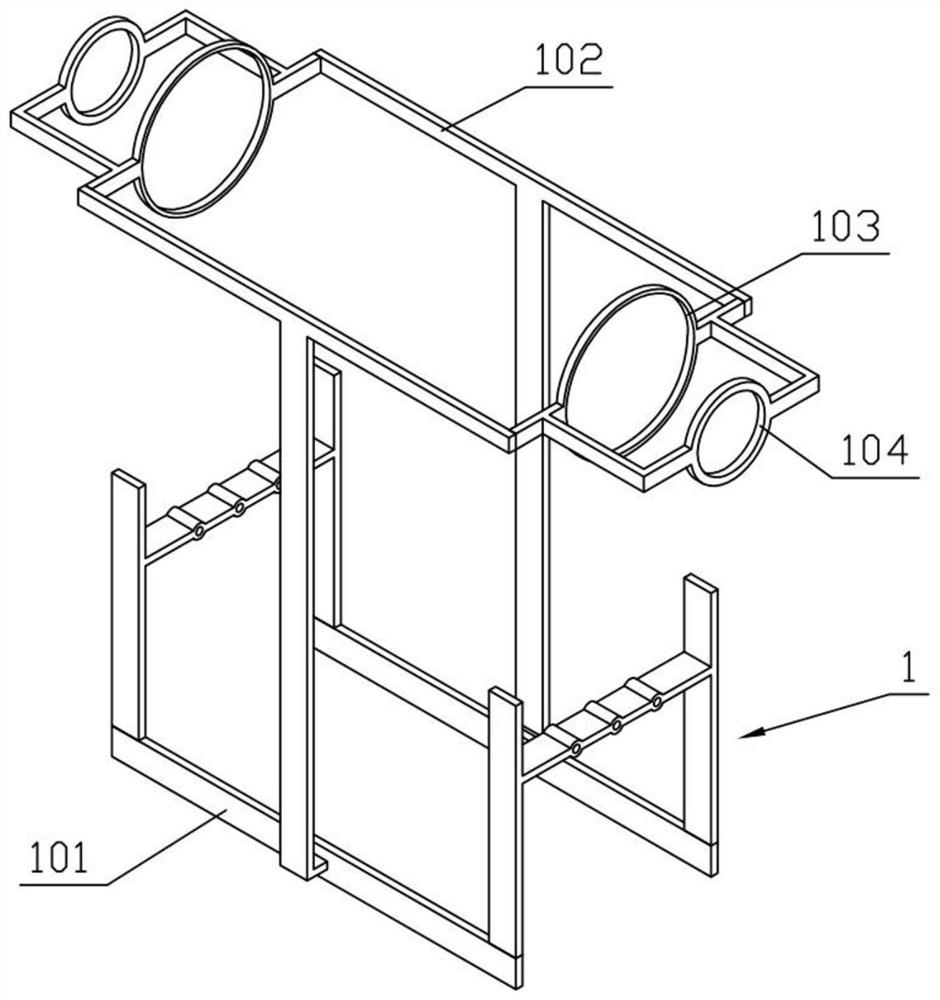
[0042] Combine below Figure 1-16 Describe this embodiment, this embodiment will further explain Embodiment 1, the device bracket 1 includes a bottom bracket 101, a top bracket 102, a connecting ring I 103 and a connecting ring II 104, the bottom bracket 101 is fixedly connected with a top bracket 102, and the top bracket The front and rear ends of 102 are fixedly connected with connecting ring I103, the two connecting rings I103 are fixedly connected with connecting ring II104, the sliding bracket I2 is provided with a long hole I201, the sliding bracket II3 is provided with a long hole II301, and the sliding bracket I2 and the sliding bracket II3 are fixedly connected to the bottom bracket 101 .

specific Embodiment approach 3

[0044] Combine below Figure 1-16 Describe this embodiment, this embodiment will further explain the second embodiment, the switching mechanism 4 includes a traverse motor 401, a limit column 402, a switch base plate 403, an adjustment screw 404 and a boat-shaped plate 405, and the traverse motor 401 is fixedly connected On the bottom bracket 101, the limit post 402 is fixedly connected on the bottom bracket 101, and the output shaft of the traverse motor 401 is connected with a switch base plate 403 by a thread, and the switch base plate 403 is slidably connected on the bottom bracket 101, and the up and down of the switch base plate 403 Both sides are rotatably connected with two adjusting screw rods 404 , and each adjusting screw rod 404 is threadedly connected with a ship-shaped plate 405 , and the four ship-shaped plates 405 are all slidably connected to the switch base plate 403 .


PUM


Abstract

The invention relates to a CO2 reactor, in particular to a photocatalytic reduction CO2 reactor which comprises a device support, a sliding support I, a sliding support II, a switching mechanism, a pushing mechanism I, a pushing mechanism II, a pushing support I, a reciprocating mechanism, a ventilation mechanism, an ultraviolet lamp sleeve, an oxidation mechanism I, an oxidation mechanism II, a pushing support II and a transmission mechanism. The pushing mechanism I and the pushing mechanism II can be pushed through the switching mechanism, wherein the pushing mechanism I compresses the pushing support I when pushed, the pushing support I drives the reciprocating mechanism to move, the reciprocating mechanism drives the two oxidation mechanisms I to move to conduct photocatalytic reduction on CO2, and the pushing mechanism II compresses the pushing support II when pushed to conduct photocatalytic reduction on CO2; then the pushing support II drives the transmission mechanism to move,the transmission mechanism drives the ventilation mechanism to move to complete gas replacement. Herein, the pushing mechanism I and the pushing mechanism II are alternately and repeatedly pushed, sothat photocatalytic reduction can be efficiently conducted on a large amount of CO2.

Description

technical field [0001] The present invention relates to CO 2 reactor, more specifically a photocatalytic reduction of CO 2 reactor. Background technique [0002] For example, the publication number CN206730862U is a photocatalytic reduction of CO 2 The reactor has a cylindrical structure as a whole, and includes a hollow cylindrical heating layer, a reflective layer attached to the inner wall of the heating layer, and coaxially extending reaction tubes and light sources installed inside the heating layer. , wherein the reaction tube extends in a spiral shape around the light source, and its first and last ends have material inlets and material outlets respectively, and a photocatalyst is attached to the inner wall, which is used to convert the CO to be reacted 2 The interior of the hollow tube through the reaction tube is kept spirally transported and reacted synchronously; the disadvantage of this utility model is that it cannot be applied to a large amount of CO 2 phot...

Claims


Application Information

Patent Timeline
Patent Type & Authority Patents(China)
IPC IPC(8): B01J19/12B01J19/00
CPCB01J19/0053B01J19/123
Inventor 姜艳丽
Owner HARBIN UNIV
Why Eureka
Try Eureka