
Stainless steel plate net fixed-specification slitting machine and slitting method

An expanded metal and stainless steel technology, applied in the direction of shearing devices, shearing machine accessories, shearing machine equipment, etc., can solve the problems that the processing specifications cannot be accurately guaranteed, the processing quality and efficiency are reduced, and the expanded metal needs to be reprocessed, etc., to achieve Solve the effect of secondary processing, improve efficiency and avoid serious deformation

Active Publication Date: 2020-11-10
佛山市诚和成金属有限公司
View PDF7 Cites 1 Cited by
  • Summary
  • Abstract
  • Description
  • Claims
  • Application Information

AI Technical Summary

Problems solved by technology

[0007] The invention can solve the problem that the existing stainless steel steel mesh is cut by a fixed knife cutting method in the cutting process, that is, the cutting knife is fixed above one end of the workbench, and the end face of the workbench is cut by the cutting knife , so as to cut the steel mesh, resulting in serious deformation at both ends of the steel mesh after cutting, affecting its subsequent use, resulting in a reduction in processing quality and efficiency, and the specification of the steel mesh can only be determined through the part of the steel mesh protruding from the end surface of the workbench. It is determined that the processing specifications cannot be accurately guaranteed, resulting in some difficult problems such as the need for reprocessing of the expanded metal mesh after slitting.

Method used


Image

  • Stainless steel plate net fixed-specification slitting machine and slitting method
  • Stainless steel plate net fixed-specification slitting machine and slitting method
  • Stainless steel plate net fixed-specification slitting machine and slitting method

Examples


Embodiment Construction

[0039] Embodiments of the present invention will be described below with reference to the drawings. In the process, in order to ensure the clarity and convenience of illustration, we may exaggerate the width of the lines or the size of the constituent elements in the diagram.

[0040] In addition, the following terms are defined based on the functions in the present invention, and may be different according to the user's or operator's intention or practice. Therefore, these terms are defined based on the entire content of this specification.

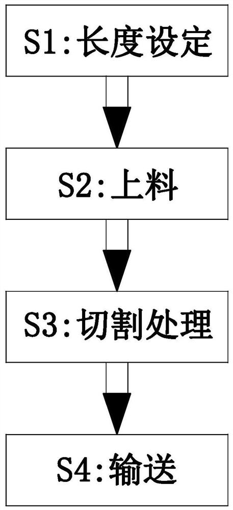
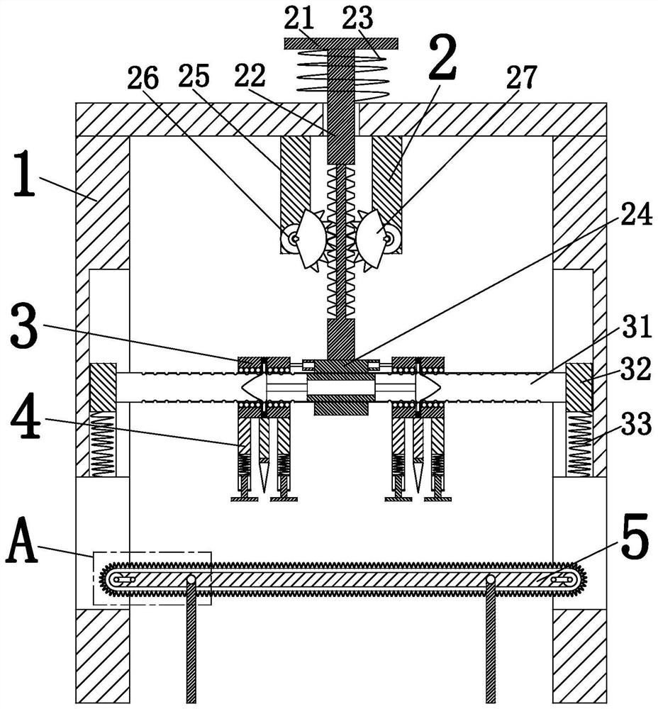
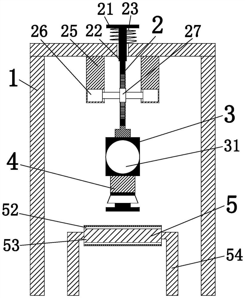
[0041] Such as Figure 1 to Figure 9 As shown, a stainless steel expanded metal mesh cutting machine with a fixed specification includes a frame body 1, a driving device 2, an adjusting device 3, a cutting device 4 and a conveying device 5, and a driving device is installed in the middle part of the inner upper end of the frame body 1 2. The lower end of the driving device 2 is symmetrically provided with an adjustment device 3; the lo...


PUM


Abstract

The invention relates to a stainless steel plate net fixed-specification slitting machine. The stainless steel plate net fixed-specification slitting machine comprises a frame body, a driving device,an adjusting device, a slitting device and a conveying device, the driving device is installed in the middle of the upper end in the frame body, the adjusting device is arranged at the lower end of the driving device in a bilateral symmetry mode, and the slitting device is fixed to the lower end of the adjusting device. According to the stainless steel plate net fixed-specification slitting machine, the problems that in the existing slitting process of a stainless steel plate net, a fixed cutter slitting method is adopted for cutting the steel plate net, in other words, a cut-off cutter is fixed above one end of a workbench, and the end face of the workbench is slit through the cut-off cutter, so that the steel plate net is cut off, the two ends of the cut-off steel plate net are seriouslydeformed, consequently the machining quality and efficiency are reduced, the specification of the steel plate net can only be determined through the part, extending out of the end face of the workbench, of the steel plate net, the machining specification of the steel plate net cannot be accurately guaranteed, and part of the slit steel plate net needs to be machined again before specific use canbe solved.

Description

technical field [0001] The invention relates to the field of stainless steel processing, in particular to a slitting machine and a slitting method for a stainless steel expanded mesh with a fixed specification. Background technique [0002] Stainless steel expanded metal mesh is a mesh product made of stainless steel, which has the characteristics of simplicity, beauty and practicality. It has a wide range of uses and is often used for filtration, breeding, packaging nets, mechanical facility protection, handicraft manufacturing, decoration, child seat and road protection, etc. It can also be used for escalators, passages, mines, locomotives, roads, municipal facilities, and It is used in residential quarters, and the shape of the mesh is mostly rhombus. In the manufacturing process, it is often necessary to cut the expanded metal mesh into rectangles of certain specifications for installation and use. [0003] At present, the existing stainless steel expanded metal mesh m...

Claims


Application Information

Patent Timeline
IPC IPC(8): B23D15/00B23D33/00B23D33/02B23Q7/00
CPCB23D15/00B23D33/00B23D33/02B23Q7/003
Inventor 李方光
Owner 佛山市诚和成金属有限公司
Learn More