
Pipe distributing and feeding method and device

A pipe and material separation technology, applied in transportation and packaging, laser welding equipment, conveyors, etc., can solve the problems of low feeding and material separation efficiency, complex structure, easy deformation of beams, etc., to improve efficiency, reduce beam load, Reduce the effect of deformation

Inactive Publication Date: 2020-11-10
SHANDONG LEIMING CNC LASER EQUIP CO LTD +2
View PDF12 Cites 9 Cited by
  • Summary
  • Abstract
  • Description
  • Claims
  • Application Information

AI Technical Summary

Problems solved by technology

[0004] In order to overcome the deficiencies in the above-mentioned prior art, the present invention provides a pipe material distribution and feeding device to solve the problems of complex structure, low feeding and distribution efficiency and easy deformation of the beam in the existing material distribution and feeding device currently used

Method used


Image

  • Pipe distributing and feeding method and device
  • Pipe distributing and feeding method and device
  • Pipe distributing and feeding method and device

Examples


specific Embodiment approach 1

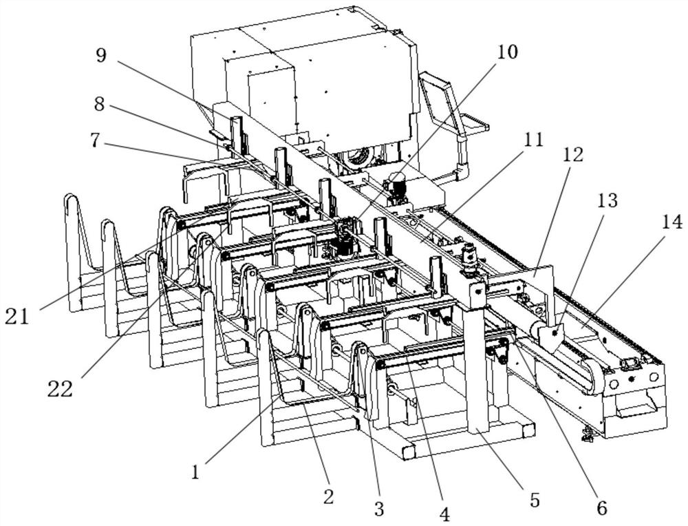
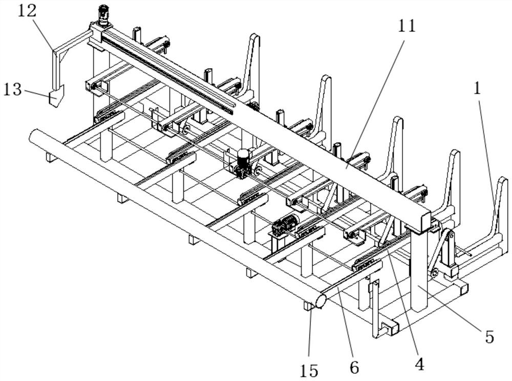
[0035] like figure 1 and figure 2As shown, the present invention provides a pipe material distribution and feeding device, which mainly includes a bundle material feeding mechanism, a support, a support platform, a material distribution mechanism, a pipe limit mechanism, and a pipe cutting machine main body 14, a support platform and a distribution platform. The material mechanism is installed on the support, and the support platform is located at the side of the discharge port of the bundle feeding mechanism. A push mechanism is installed on the support platform, which can send the pipes on the support platform to the main body 14 of the pipe cutting machine. The positioning mechanism also measures the length of the pipe while limiting the position of the pipe on the main body 14 of the pipe cutting machine. Wherein, the bearing is divided into base 5 and crossbeam 11 two parts, and crossbeam 11 is installed on the top of base 5 and is supported by base 5 to crossbeam 11; ...

specific Embodiment approach 2

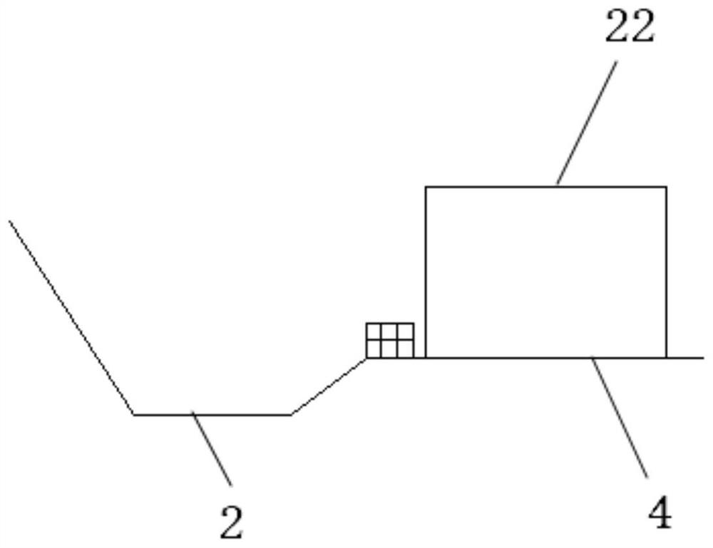
[0038] On the basis of the specific embodiment 1, this specific embodiment provides a pipe material distribution and feeding method, the method is: the bundled pipes are placed in the placement groove 2, and the lifting belt 1 is driven by the power unit to drive the bundled pipes Moving from the placement slot 2 to the upper feeding port, the material distribution fork 22 moves to the feeding port of the bale feeding mechanism through lifting and translation, and will be pushed by the front end of the material distribution fork 22. One or two pipes pass into the support beam 4 and are supported by the support beam 4. Wherein, the distribution shift fork 22 is lowered to its bottom lower than the bottom pipe to be able to push all the pipes to move, and the distribution shift fork 22 Move backwards, use the front end of the separation fork 22 to push the pipe to push the part of the pipe at the rear back into the placement groove 2, then the distribution fork 22 rises to slight...


PUM


Abstract

The invention provides a pipe distributing and feeding method and device. According to the adopted scheme, the pipe distributing and feeding device comprises a bundling and feeding mechanism, a supporting seat, a supporting platform and a distributing mechanism, wherein the supporting platform and the distributing mechanism are arranged on the supporting seat, and the supporting platform is positioned on one side of a discharging port of the bundling and feeding mechanism; a push mechanism is arranged on the supporting platform and can slide left and right on the supporting platform, and a positioning structure is arranged on the push mechanism; and the distributing mechanism comprises a distributing shift fork which can move up and down and left and right. The distributing shift fork canpush a single pipe from one side of the supporting platform to the positioning structure. The movement of the distributing shift fork drives the pipe to move to realize feeding and distribution, so that a complex structure for specially limiting the pipe height and distribution in original equipment is replaced, the process of raising the pipe height is saved, and thus the efficiency is improved.

Description

technical field [0001] The invention relates to the field of laser cutting and feeding equipment, in particular to a method and device for separating and feeding pipe materials. Background technique [0002] Nowadays, in the field of laser cutting pipes, the material distribution and feeding action for six-meter conventional pipes (mainly round pipes of conventional sizes, square pipes, etc.) has been very mature, and there are many material distribution and feeding devices on the market, but All have the disadvantages of large floor area, complex structure, and long feeding time. In addition, the existing devices all use a beam on which movable grippers are installed to clamp the pipe and then move it with the pipe. Due to the increase in the weight of the pipe on the beam, the beam bears an excessive load. The load of time will cause the deformation of the beam, resulting in inaccurate clamping of the pipe by the gripper. [0003] Therefore, in view of the current situat...

Claims


Application Information

Patent Timeline
Patent Type & Authority Applications(China)
IPC IPC(8): B23K26/38B23K26/70B65G47/82B65G47/22B65G47/74
CPCB23K26/38B65G47/22B65G47/74B65G47/82B65G2201/0276B23K26/702
Inventor 李荣昌王庆伟李峰西高凯邢振宏索海生豪斯特·埃克斯纳
Owner SHANDONG LEIMING CNC LASER EQUIP CO LTD
Learn More