Sound field equalizer for loudspeak system

A technology for equalizing devices and speakers, applied in stereo devices, stereo systems, spatial/structural arrangements of speakers, etc., can solve the problems of sound directionality and spatial attenuation.

Inactive Publication Date: 2003-08-20
LG ELECTRONICS INC
View PDF2 Cites 0 Cited by
  • Summary
  • Abstract
  • Description
  • Claims
  • Application Information

AI Technical Summary

Problems solved by technology

Therefore, in existing loudspeaker systems, the sound is less directional and spatial

Method used


Image

  • Sound field equalizer for loudspeak system
  • Sound field equalizer for loudspeak system
  • Sound field equalizer for loudspeak system

Examples


Embodiment Construction

[0029] A sound field equalization device for a speaker system according to the present invention will now be described with reference to the accompanying drawings.

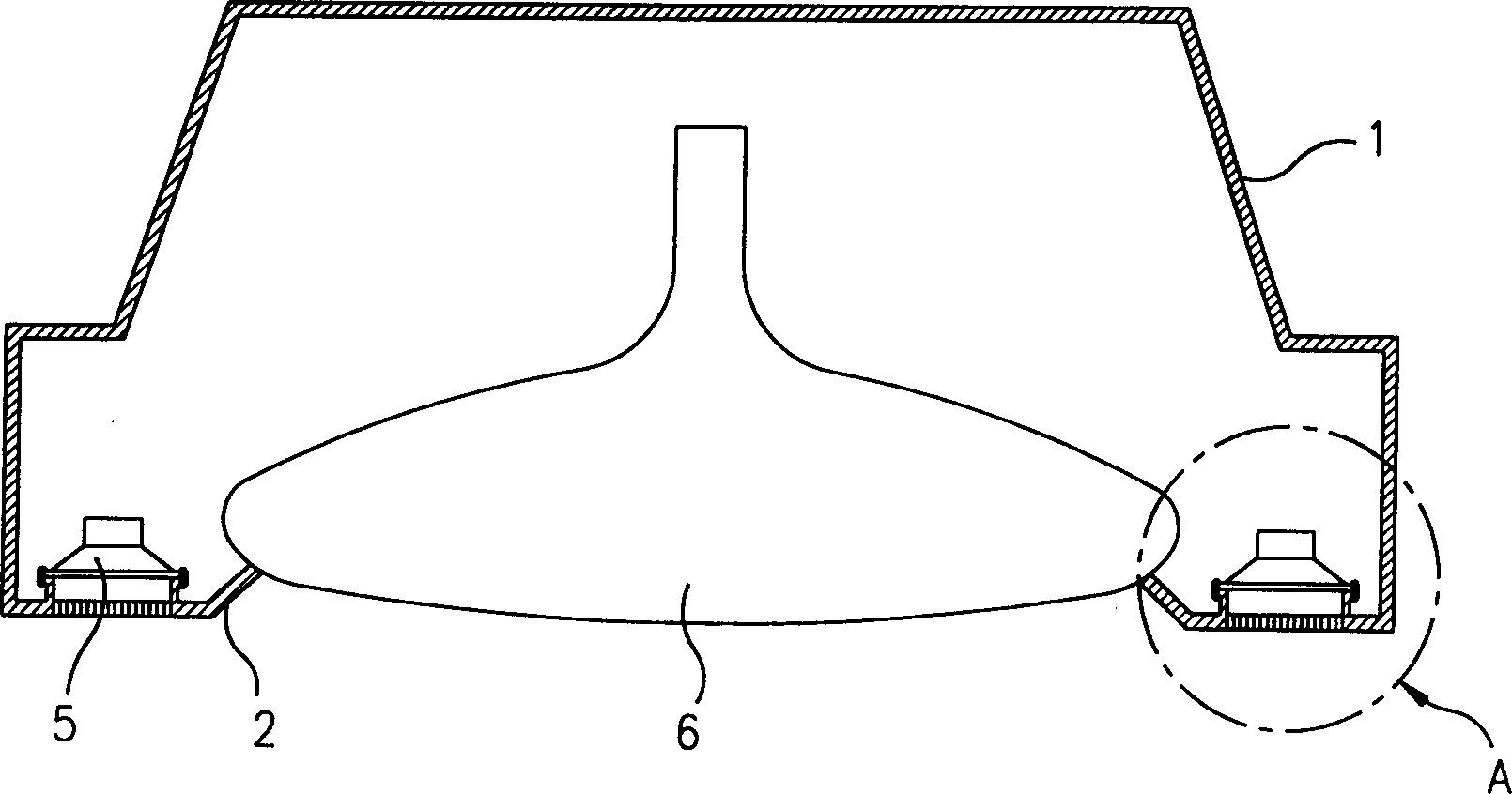
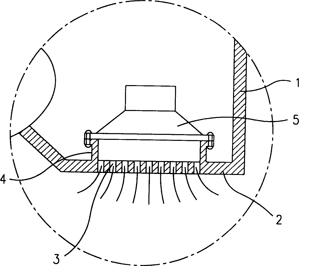
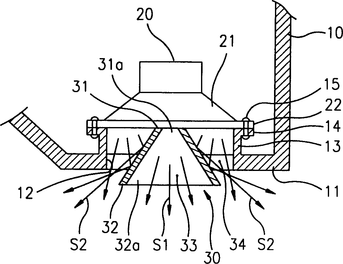
[0030] First, if image 3 As shown in , in the sound field equalization device for a speaker system according to the present invention, a sound propagation hole 12 is formed on the front panel 11 of the box body 10 , and the speaker 20 is installed inside the front panel 11 . At this time, the sound propagation hole 12 on the front panel 11 is circular. The diameter of each sound propagation hole 12 is the same as that of the vibrating piece (not shown).

[0031] Speaker fixing ribs 13 are formed on the inner surface of the front panel 11 to fix the speaker 20 thereon. An outwardly bent portion 14 is formed around the upper edge of the fixing rib 13, and a fixing screw 15 passing through a flange portion 22 formed on the edge of the speaker cone 21 engages with the outwardly bent portion 14, thereby fixing the sp...


PUM


Abstract

A sound field equalizing apparatus for a speaker system which is capable of widening a region in which it is possible to effectively hear a sound field. The apparatus includes a sound field equalizing member disposed in a dispersing hole formed in a cabinet of a speaker for separating a sound dispersed from the speaker into a forwardly dispersed sound which is dispersed in a central direction and a laterally dispersing sound which is dispersed in a peripheral direction of the forwardly dispersing sound.

Description

technical field [0001] The invention relates to a sound field equalization device for a loudspeaker system, in particular to an improved sound field equalization device for a loudspeaker system, which can evenly spread the sound generated by the loudspeaker to every corner of the room where the loudspeaker system is arranged. Background technique [0002] FIG. 1 shows a speaker system of a conventional television receiver, and FIG. 2 shows part "A" of FIG. 1 . As shown in the figure, a plurality of sound propagation holes 3 are formed on the front panel 2 of the box body 1 . A speaker fixing rib 4 is formed on the inner surface of the front panel 2 so that the speaker 5 can be fixed on the speaker fixing rib 4 . In the figure, reference numeral 6 denotes a Braun tube (cathode ray tube). [0003] Sound emitted from the speaker 5 propagates through the sound propagation hole 3 . [0004] At this time, the sound generated by the speaker 5 and propagated through the sound pro...

Claims


Application Information

Patent Timeline
IPC IPC(8): H04R5/00H04R5/02H04S3/00
CPCH04R2499/15H04R1/345H04R5/02H04R5/00H04S3/00
Inventor 李德镇
Owner LG ELECTRONICS INC
Why Eureka
Try Eureka