Robot-assisted continuous resistance welding equipment and welding method for thermoplastic materials

A robot-assisted, thermoplastic material technology, applied in the field of composite material manufacturing, can solve problems such as uneven temperature distribution, high applied pressure, and uneven welding pressure, so as to improve welding efficiency and welding quality, high welding efficiency and good welding quality Effect

Pending Publication Date: 2020-11-10
DALIAN UNIV OF TECH
View PDF2 Cites 0 Cited by
  • Summary
  • Abstract
  • Description
  • Claims
  • Application Information

AI Technical Summary

Problems solved by technology

However, practical applications require that the welding area is much larger than that of the test piece (within the range of a few square centimeters), and the traditional research equipment for resistance welding cannot meet the application requirements.
On the other hand, in the process of process enlargement, factors such as input power, welding pressure, temperature distribution, and edge effects will also change due to size effects, which will affect welding quality. We need to develop new equipment and carr

Method used


Image

  • Robot-assisted continuous resistance welding equipment and welding method for thermoplastic materials
  • Robot-assisted continuous resistance welding equipment and welding method for thermoplastic materials
  • Robot-assisted continuous resistance welding equipment and welding method for thermoplastic materials

Examples


Example Embodiment

[0038] Example 1: Welding of hat-shaped piece and curved plate (double roll)

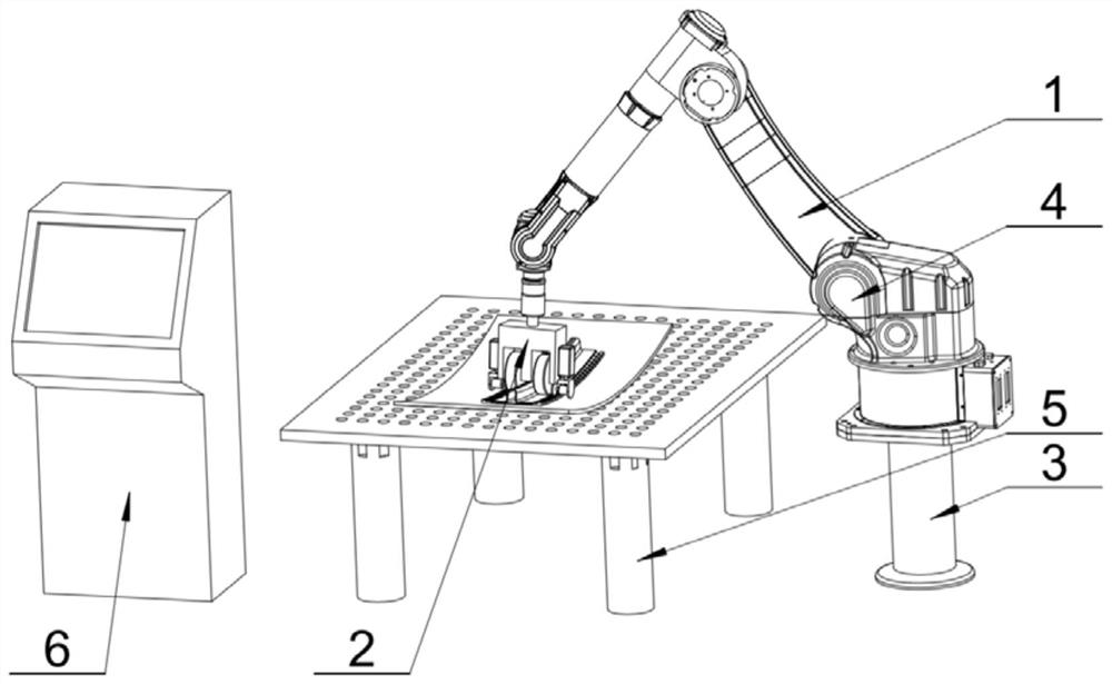
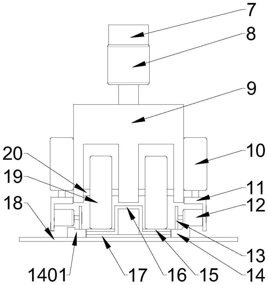
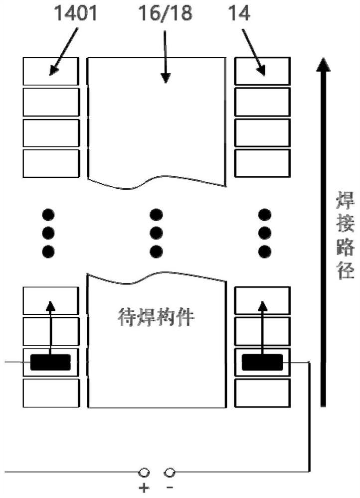
[0039] Such as figure 1 with figure 2 As shown, first, the second member 18 to be welded is fixed on the welding work platform 5, and the input electrode 14 and the output electrode 1401 are respectively bonded to the surface of the second member 18 to be welded using water-soluble glue. Such as image 3 As shown, a gap of 1 mm is provided between adjacent electrodes to realize segmented continuous energization of the heating material 17. After the welding work starts, parameters such as input power, movement speed, welding pressure, energization time and energization frequency are set through the industrial control cabinet 6. The robot arm 4 walks along the preset welding path, and the hydraulic cylinder 8 applies the preset welding pressure. At the same time, the actual welding pressure is fed back through the pressure sensor 7, and the industrial control cabinet 6 is further adjusted to make the ap...

Example Embodiment

[0040] Example 2: Welding of L-shaped parts and curved plates (single roll)

[0041] Such as Figure 4 As shown, the robot-assisted continuous resistance welding equipment of this embodiment includes two parts: a motion control module 1 and a continuous pressure welding module 2. The difference from the first embodiment is that the continuous pressure welding module uses a single pressure roller 19 to continuously apply stable pressure to the first member 16 to be welded.

[0042] In summary, the discontinuous and continuous distribution of the multiple sets of electrodes of the continuous pressure welding module of the present embodiment along the weld seam can realize segmented continuous heating welding of the components to be welded. At the same time, it can realize the integrated control of welding pressure, welding speed, welding power, welding temperature and other process parameters, and can weld full-size weld structure parts, which solves the problem of uneven heating te...


PUM


Abstract

The invention discloses robot-assisted continuous resistance welding equipment and welding method for thermoplastic materials. The robot-assisted continuous resistance welding equipment comprises a motion control module and a continuous pressure welding module. The motion control module adopts a mechanical arm to provide a motion path for the continuous pressure welding module, the continuous pressure welding module comprises input and output electrodes which are discontinuously arranged along the welding path, and after a weld joint area is discretized, a hydraulic cylinder applies pressure to the weld joint area, and welding pressure is transmitted through a pressure roller. The robot-assisted continuous resistance welding equipment and method can be applied to welding of large thermoplastic plastic or composite structural parts with curvature, have the advantages of real-time monitoring of welding parameters, automatic control, high welding efficiency, good welding quality and the like, meet the requirements of industrial production, and solve the problems that traditional static resistance welding is uneven in temperature, and is only limited to welding of small curvature-freecomponents, and welding parameters are uncontrollable.

Description

technical field [0001] The invention belongs to the technical field of composite material manufacturing, and in particular relates to robot-assisted continuous resistance welding equipment and a welding method for thermoplastic materials. Background technique [0002] In the field of thermoplastic material component manufacturing, there are a large number of connections between thermoplastic materials, and the typical connection forms include reinforced components (Z-shaped pieces, L-shaped pieces, T-shaped pieces, hat-shaped pieces, Π-shaped pieces) and plate-type components. The connection of mechanical riveting and adhesive bonding is widely used at present. Among them, the fatal problem of mechanical riveting technology lies in the introduction of defects in the composite material, which easily forms a large stress concentration at the riveting position, resulting in greatly reduced performance of the material; and the defect of bonding technology lies in the longer proc...

Claims


Application Information

Patent Timeline
IPC IPC(8): B29C65/18
CPCB29C65/18B29C66/9221B29C66/90B29C66/91313B29C66/91315Y02P70/10
Inventor 赵刚徐剑张守海陈友汜蹇锡高
Owner DALIAN UNIV OF TECH
Why Eureka
Try Eureka