Punch forming over-current ultraviolet sterilizer and manufacturing process for sterilization device of punch forming over-current ultraviolet sterilizer

A technology of stamping forming and disinfection device, applied in the direction of light water/sewage treatment, etc., can solve problems such as unfavorable post-maintenance, unguaranteed welding quality, poor drilling positioning accuracy, etc., so as to improve welding efficiency and welding quality, and improve production. Efficiency and production quality, the effect of reducing labor intensity

Active Publication Date: 2016-02-03
TIANJIN MORUI ENVIRONMENTAL TECH
View PDF6 Cites 0 Cited by
  • Summary
  • Abstract
  • Description
  • Claims
  • Application Information

AI Technical Summary

Problems solved by technology

[0004] 1. In the production of the end of the ultraviolet sterilizer in the current technology, holes must be drilled on the solitary head first, and then the wire head is welded to fix the quartz sleeve and the sealing kit. The disadvantages: the positioning accuracy of the drilling is poor, and the efficiency is very low. In addition, the wire head must be ground according to the arc of the head before welding, which is difficult to produce, and the efficiency is low and the cost is high. In addition, because the welding part of the welding part has an irregular arc surface, automatic welding equipment cannot be used for welding, and the welding quality cannot be guaranteed;
[0005] 2. The water inlet and outlet n

Method used


Image

  • Punch forming over-current ultraviolet sterilizer and manufacturing process for sterilization device of punch forming over-current ultraviolet sterilizer
  • Punch forming over-current ultraviolet sterilizer and manufacturing process for sterilization device of punch forming over-current ultraviolet sterilizer
  • Punch forming over-current ultraviolet sterilizer and manufacturing process for sterilization device of punch forming over-current ultraviolet sterilizer

Examples


Example Embodiment

[0037] The technical solutions in the embodiments of the present invention will be clearly and completely described below in conjunction with the accompanying drawings in the embodiments of the present invention. Obviously, the described embodiments are only a part of the embodiments of the present invention, rather than all the embodiments. Based on the embodiments of the present invention, all other embodiments obtained by those of ordinary skill in the art without creative work shall fall within the protection scope of the present invention.
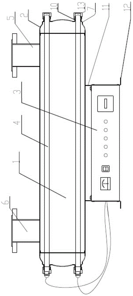
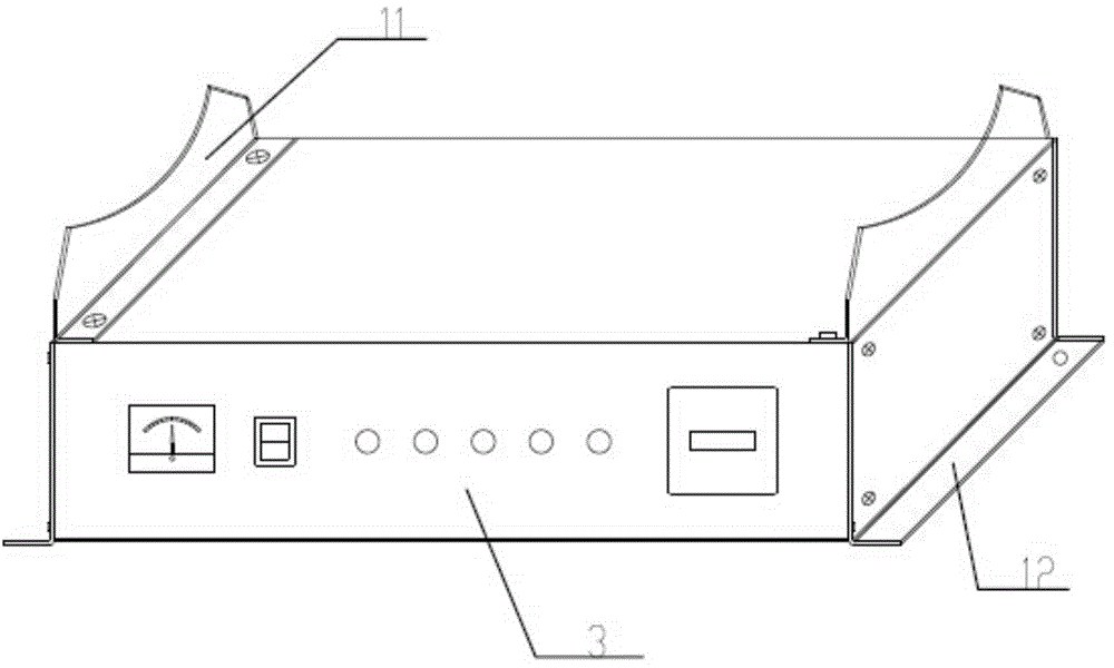
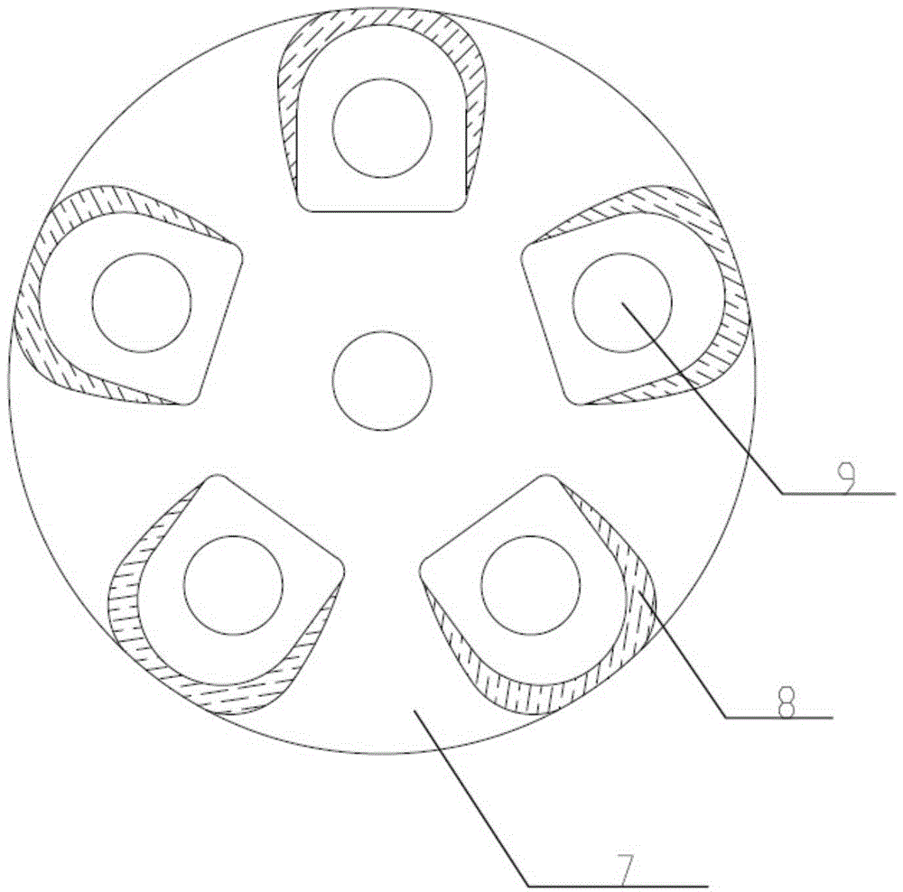
[0038] Such as Figure 1~3 As shown, the stamping and forming over-current ultraviolet sterilizer provided by the present invention includes:

[0039] The disinfection device includes a main body 1. The main body 1 is provided with water inlets and outlets for installing the water inlet device 5 and the water outlet device 6; both ends of the main body 1 are provided with a structurally symmetrical end 2 which is a stamped and formed end ...


PUM


Abstract

The invention provides a punch forming over-current ultraviolet sterilizer which comprises a sterilization device and a distribution box, wherein the sterilization device comprises a main body provided with a water inlet and a water outlet for mounting of a water inlet device and a water outlet device and ultraviolet lamp tube sleeves; ends in structural symmetry are arranged at the two ends of the main body; the ends are punch forming ends; a plurality of benchmark stages uniformly distributed are arranged at the ends; a through hole is formed in each benchmark stage; a wire end used for arrangement of a sealing sleeve is arranged on each benchmark stage through welding; the ultraviolet lamp tube sleeves are arranged on the two benchmark stages, the ends of which are symmetrical; the distribution box is connected with the ultraviolet lamp tube sleeves and arranged below the main body through a barrel bracket; a manufacturing process for the sterilization device of the sterilizer comprises the following steps: primary punching and secondary punching of the ends, spinning forming of the ends, punch forming of the water inlet and the water outlet, welding, assembling and the like. Through the design, batch production of the sterilizer is realized, the quality of the sterilizer is improved, the production cost is reduced and later maintenance is facilitated.

Description

technical field [0001] The invention relates to the technical field of water treatment equipment, in particular to a stamping forming over-flow ultraviolet sterilizer and a manufacturing process of the sterilizing device. Background technique [0002] Ultraviolet sterilizers are widely used and have a high value in water treatment. It destroys and changes the DNA (deoxyribonucleic acid) structure of microorganisms through ultraviolet light irradiation, so that the bacteria die immediately or cannot reproduce offspring to achieve the purpose of sterilization . It is UVC ultraviolet rays that really have a bactericidal effect, because C-band ultraviolet rays are easily absorbed by the DNA of organisms, especially ultraviolet rays around 253.7nm are the best. Ultraviolet sterilizer is a purely physical disinfection method, which has the advantages of simplicity, convenience, broad spectrum and high efficiency, no secondary pollution, easy management and automation. With the in...

Claims


Application Information

Patent Timeline
IPC IPC(8): C02F1/32
Inventor 蒋国明
Owner TIANJIN MORUI ENVIRONMENTAL TECH
Why Eureka
Try Eureka