Vibration feeding device

A technology of vibrating feeding and vibrating material, applied in the direction of vibrating conveyor, packaging, conveyor, etc., can solve the problems of easy blockage of materials, intermittent feeding, feeding interruption, etc., to avoid material blocking, stable and uniform feeding, Guaranteed effect of feeding speed

Pending Publication Date: 2020-11-10
HEFEI MEIYA OPTOELECTRONICS TECH
View PDF0 Cites 3 Cited by
  • Summary
  • Abstract
  • Description
  • Claims
  • Application Information

AI Technical Summary

Problems solved by technology

However, when the electromagnetic vibrator is used as the feeding and conveying equipment, when the material is highly viscous or easy to hook up, due to the limited amplitude of the electromagnetic vibrator, the material is easily blocked between the lower edge of the baffle and the surface of the vibrating hopper, resulting in intermittent or intermittent feeding. Material interruption

Method used


Image

  • Vibration feeding device
  • Vibration feeding device
  • Vibration feeding device

Examples


Embodiment 1

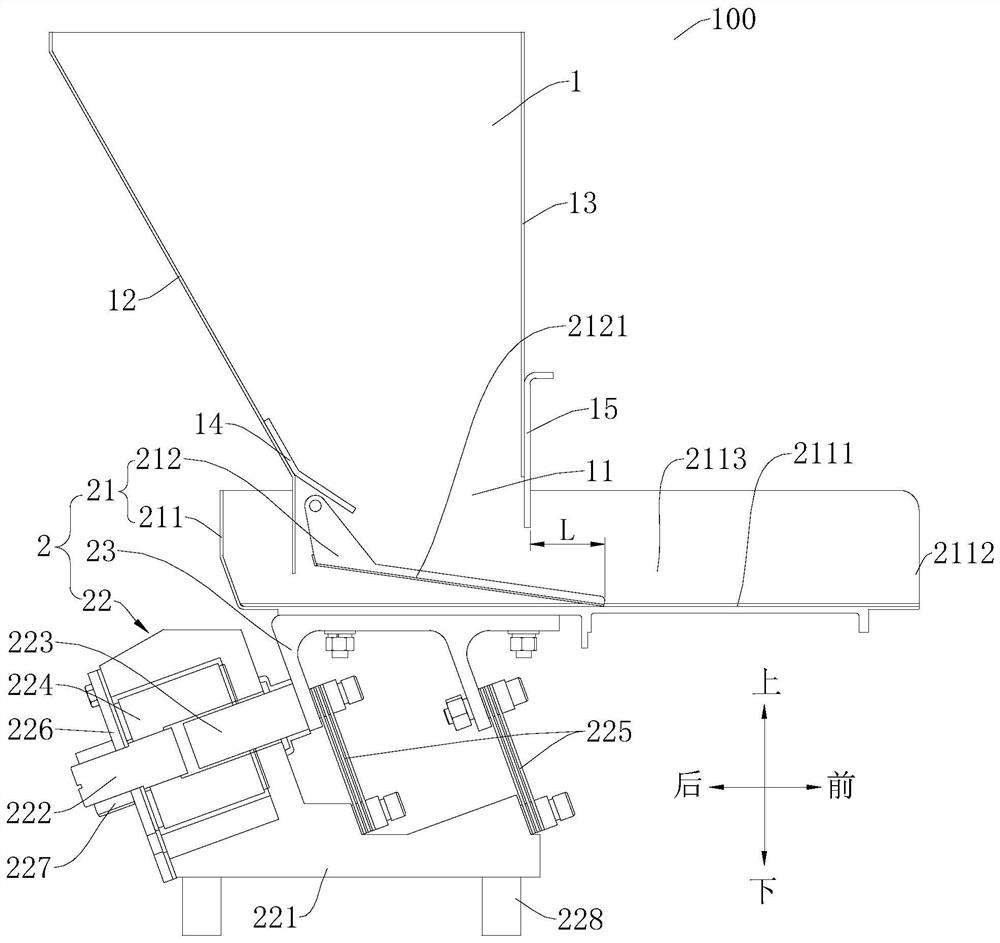
[0097] Such as Figure 1-Figure 3 As shown, the vibration feeding device 100 of the present embodiment consists of a base 221, a lock nut 227, a drive shaft 222, a rear cover plate 226, a coil 224, an armature (magnetic part 223), a primary hopper body 211, and a primary hopper seat 23. An elastic sheet (elastic reset part 225), an elastic foot 228, a feed bin 1, a primary baffle plate 15, a primary slide plate 212 and a material guide plate 14 are formed.

[0098] Wherein, the rear cover 226 is connected to the base 221 by bolts. The drive shaft 222 is threadedly engaged with the rear cover 226 , and the locking nut 227 is used to lock the relative position between the drive shaft 222 and the rear cover 226 . The drive shaft 222 axis is collinear with the armature axis. The armature is fixedly connected to the primary hopper seat 23 by bolts, the primary hopper body 211 is connected to the primary hopper seat 23, the upper and lower ends of the elastic sheet are fixedly con...

Embodiment 2

[0105] Such as Figure 4 As shown, the structure of this embodiment is roughly the same as that of Embodiment 1, wherein the same components use the same reference numerals, the only difference is that: the vibration feeding device 100 described in Embodiment 1 only includes a primary vibration material assembly, However, the vibrating feeding device 100 in the second embodiment includes two levels of vibrating material components: a primary vibrating material component 2 and a secondary vibrating material component 3 .

[0106] Specifically, such as Figure 4 As shown, the vibration feeding device 100 of the embodiment of the present invention includes: a primary vibrator 22, a primary hopper body 211, a primary slide plate 212, a material guide plate 14, a feed bin 1, a primary baffle plate 15, and a slide plate support 33 , secondary slide plate 312, secondary vibrator 32, secondary hopper body 311, baffle support 34, secondary baffle 35 and material level sensor 36.

[0...

Embodiment 3

[0113] Such as Figure 5-Figure 7 As shown, the structure of this embodiment is substantially the same as that of Embodiment 1, wherein the same components use the same reference numerals, and the only difference is that the lower end of the first-stage slide plate 212 in Embodiment 1 rests on the first-stage vibrating material On the bottom wall of the cavity 2113, the lower end of the primary slide plate 212 is roughly in line contact or surface contact with the bottom wall of the primary vibrating material cavity 2113, while the lower end of the primary slide plate 212 in the third embodiment rests on the primary vibrating material cavity. On the side wall of the material cavity 2113 , there is a point contact between the primary slide plate 212 and the side wall of the primary hopper body 211 .

[0114] Specifically, such as Figure 5 As shown, the vibration feeding device 100 of the embodiment of the present invention includes: a primary vibrator 22, a primary hopper bod...


PUM


Abstract

The invention discloses a vibration feeding device. The vibration feeding device comprises a feeding bin, a first-stage material vibrating hopper and a first-stage vibrator. The first-stage material vibrating hopper is arranged below the feeding bin and comprises a first-stage hopper body and a first-stage sliding plate. A first-stage material vibrating cavity with an open top is formed in the first-stage hopper body, one side of the first-stage material vibrating cavity is open to form a first-stage discharging port communicated with the first-stage material vibrating cavity, and at least part of the first-stage sliding plate is arranged in the first-stage material vibrating cavity. The first-stage sliding plate obliquely extends downwards, the first-stage sliding plate can rotate arounda first-stage fixed axis close to the upper end of the first-stage sliding plate, and the lower end of the first-stage sliding plate is detachably erected on the first-stage hopper body; and the first-stage vibrator is connected with the first-stage material vibrating hopper. According to the vibration feeding device, materials can be prevented from being blocked, impurity materials are preventedfrom flowing into a finished product, the feeding speed is guaranteed, and stable and uniform conveying and feeding of the materials which are bonded and are easy to hook and connect are achieved.

Description

technical field [0001] The invention relates to a vibration feeding device. Background technique [0002] In the related art, the electromagnetic vibrator conveys and feeds materials generally includes an electromagnetic vibrator, a vibrating hopper, a feeding bin, and a baffle. Its working principle is that the material in the feeding bin moves to the right through the outlet between the lower edge of the baffle plate and the surface of the vibrating hopper under the action of the electromagnetic vibrator to realize the conveying and feeding. However, when the electromagnetic vibrator is used as the feeding and conveying equipment, when the material is highly viscous or easy to hook up, due to the limited amplitude of the electromagnetic vibrator, the material is easily blocked between the lower edge of the baffle and the surface of the vibrating hopper, resulting in intermittent or intermittent feeding. Material interruption. Contents of the invention [0003] The pres...

Claims


Application Information

Patent Timeline
Patent Type & Authority Applications(China)
IPC IPC(8): B65G65/44B65G27/16B65D88/66
CPCB65D88/66B65G27/16B65G65/44
Inventor 唐政飞江奎
Owner HEFEI MEIYA OPTOELECTRONICS TECH
Why Eureka
Try Eureka