Heavy-duty construction loading and unloading trolleys

A technology for structures and loading and unloading platforms, which is applied to buildings, lifting devices, building structures, etc., can solve problems such as insufficient force, insufficient control precision, and difficulty in carrying heavy structures, so as to reduce occupancy, complexity, and Observe the effect of the steps

Active Publication Date: 2022-07-08
CCCC WUHAN HARBOR ENG DESIGN & RES +1
View PDF10 Cites 0 Cited by
  • Summary
  • Abstract
  • Description
  • Claims
  • Application Information

AI Technical Summary

Problems solved by technology

However, when transferring this structure to the installation field of heavy-duty structures, there are problems of insufficient control precision during installation, insufficient force, and difficulty in carrying heavy-duty structures. There are also major problems in how to quickly connect and fix heavy-duty structures.

Method used


Image

  • Heavy-duty construction loading and unloading trolleys
  • Heavy-duty construction loading and unloading trolleys
  • Heavy-duty construction loading and unloading trolleys

Examples


Embodiment 1

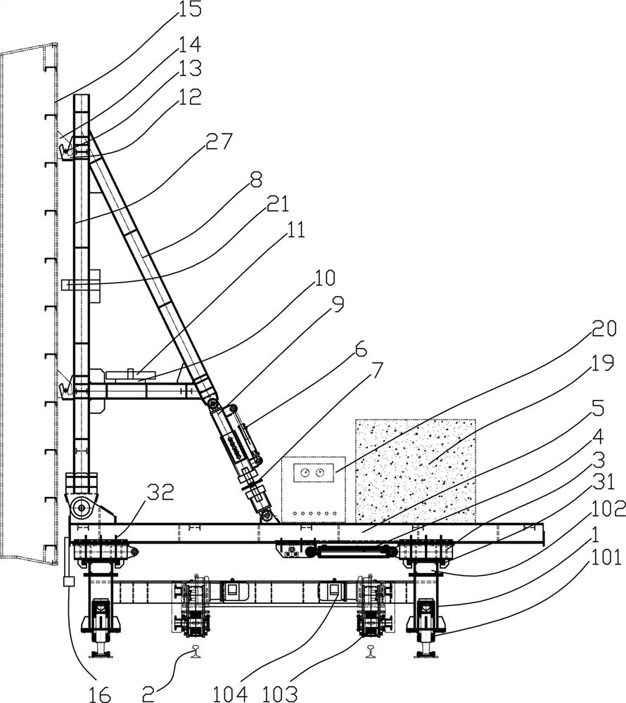
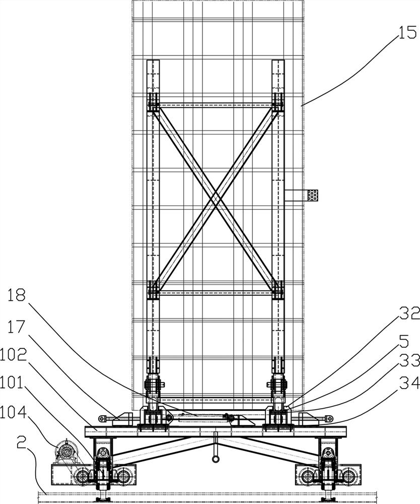
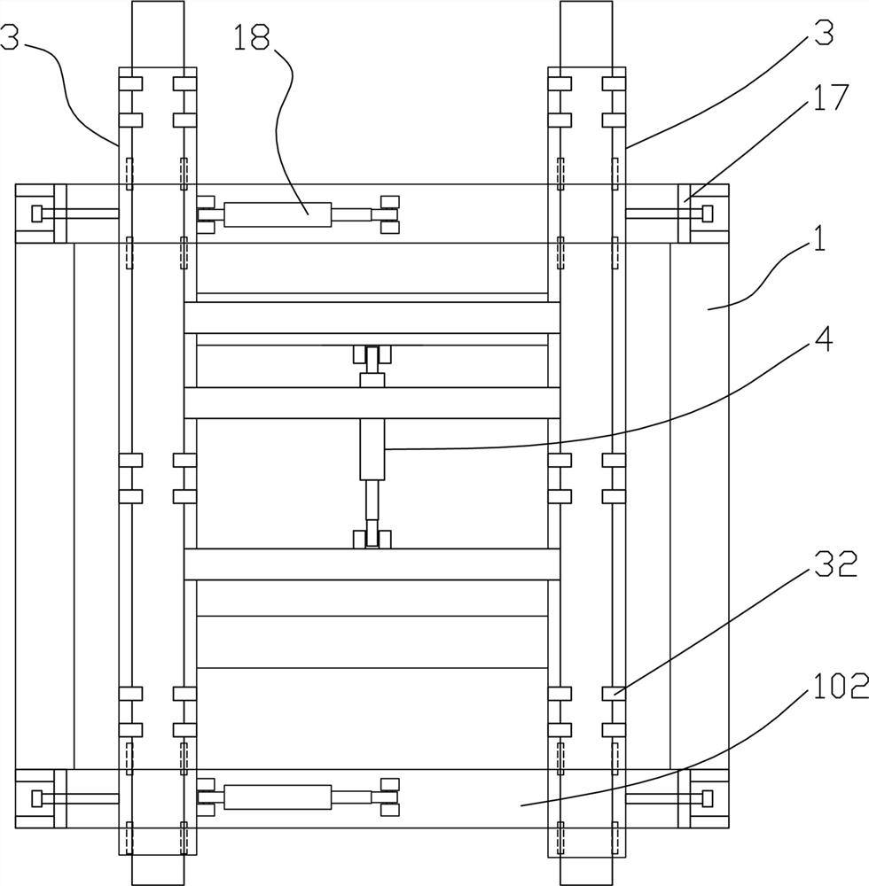
[0077] The steps of setting the barb device 14 on the heavy structure 15, such as Figure 11 , 12 As shown in the figure, the position of the barb device 14 is set, and a separate template is set. The template adopts the structure of a seam template, and a plurality of holes are provided on the template, and a plurality of connecting bolts 25 pass through the holes and are respectively connected with the embedded gasket. The plate nuts 23 are fixedly connected. In this example, each template is provided with at least 4 pre-embedded backing plate nuts 23. This structure ensures that the distance between each pre-embedded backing plate nut 23 is a fixed value. The distance between each bearing pin 13 or bearing seat 12 on the frame 8 is also a fixed value corresponding to the distance between the connecting bolts 25 one-to-one. In order to connect the successor with the loading and unloading frame 8 reliably. The formwork is positioned close to the center of mass of the heavy ...

Embodiment 2

[0079] The loading and unloading frame 8 is provided with a bearing pin 13, a frame mold is used, and a double lug plate corresponding to the position of the bearing pin 13 is set on the mold, such as four double lugs, and the bearing seat 12 is passed through the bearing pin 13 and the double lug plate. Connect to fix the relative position of the bearing seat 12, place the mold as a whole on the front end face of the loading and unloading frame 8, the bearing seat 12 is in contact with the loading and unloading frame 8, connect the bearing seat 12 with the loading and unloading frame 8 by spot welding, and remove the bearing pin 13 Then, the bearing seat 12 and the loading and unloading frame 8 are fully welded. During the welding process, the deformation of the bearing seat 12 is controlled by staggered welding seams. By the above method, it is ensured that the bearing pin 13 and the barb device 14 correspond in position, and the force between them is reliable, and the force ...

Embodiment 3

[0081] The auxiliary positioning target 22 is set, and according to the parameter of the spatial distance between the position of the positioning sensor 16 and the installation position, the auxiliary positioning target 22 is offset by a corresponding spatial distance and set near the position to be installed. The traveling frame 1 is located at the hoisting position of the traveling track 2, such as Image 6 shown in. The hoisting device hoists the heavy construction 15 , such as the end sealing door of the sunk pipe, onto the loading and unloading frame 8 , so that the barb device 14 is hooked on the bearing pin 13 . After the installation is fixed, the driving device 104 drives the traveling frame 1 to travel along the traveling track 2 to the installation station. According to the inclination angle of the installation position, the hydraulic oil output from the hydraulic station 20 controls the expansion and contraction of the piston rod of the tilt cylinder 6, so that th...


PUM


Abstract

The invention provides a heavy-duty structure loading and unloading trolley, which includes a traveling frame, a traveling wheel and a jacking oil cylinder are arranged at the bottom of the traveling frame, and a sliding seat is arranged on the top of the traveling frame, which is used to move along the traveling frame. The top of the sliding seat is provided with a telescopic frame for longitudinal displacement along the traveling frame; the telescopic frame is provided with a loading and unloading frame, the front end of the bottom of the loading and unloading frame is hinged with the front end of the telescopic frame, and the bottom of the loading and unloading frame is hinged with the front end of the telescopic frame. The rear end is hinged with the loading and unloading frame through an inclination adjustment rod, and the inclination angle adjustment rod is used to adjust the pitch angle of the loading and unloading frame. By adopting the adjustable up and down, front, rear, left, right and pitch angles, the spatial position of the heavy structure can be precisely adjusted to meet the needs of the installation and removal of the heavy structure. Reduce the occupation of on-site hoisting equipment and greatly improve construction efficiency.

Description

technical field [0001] The invention relates to the field of installation and disassembly of heavy-duty structures, in particular to a heavy-duty structure loading and unloading trolley. Background technique [0002] The heavy structures referred to in this example include structures that are difficult or inconvenient to handle by manpower, such as steel end sealing doors for underground pipes or corridors; fabricated shear walls, fabricated beams, fabricated columns or other fabricated components; large-scale integrated glass curtain wall units, etc. Taking the immersed steel end-sealing door as an example, the current installation mostly adopts the traditional construction method: that is, firstly install the corbel and steel beam, and finally rely on the installed components to position and install the end-sealing door with a spreader and a chain hoist, which is also a lot of heavy construction. main installation method. This construction method requires a lot of manpow...

Claims


Application Information

Patent Timeline
Patent Type & Authority Patents(China)
IPC IPC(8): B66F9/06B66F9/075B66F9/12B66F9/22E04G21/16E04G21/18
CPCB66F9/06B66F9/07577B66F9/0755B66F9/07554B66F9/12B66F9/075B66F9/22E04G21/162E04G21/1841Y02E10/20
Inventor 梁丰刘斌李海方谢小琴阮明华纪岩王虎臣
Owner CCCC WUHAN HARBOR ENG DESIGN & RES
Why Eureka
Try Eureka