A simple manipulator of an industrial robot

A technology of industrial robots and manipulators, which is applied in the field of robots, can solve problems such as complex structure of the gripper, high cost of manual handling, and harm to human health, and achieve the effects of flexible use, flexible use, and high safety

Active Publication Date: 2022-05-24
GUANGDONG POLYTECHNIC NORMAL UNIV
View PDF0 Cites 0 Cited by
  • Summary
  • Abstract
  • Description
  • Claims
  • Application Information

AI Technical Summary

Problems solved by technology

[0002] Since the raw materials, intermediate products and final products in industrial production have to go through the process of handling, the previous handling was mainly by manpower, and some products or raw materials that need to be transported are in powder form; in this way, on the one hand, the powder will spread Into the air, manual handling will endanger human health; on the other hand, the cost of manual handling is high and the efficiency is low; and the packaging shapes of raw materials, intermediate products and final products are different, and different grippers need to be replaced for handling, but the replacement of grippers On the one hand, time is wasted, and on the other hand, the structure of the gripper is complicated

Method used


Image

  • A simple manipulator of an industrial robot
  • A simple manipulator of an industrial robot
  • A simple manipulator of an industrial robot

Examples


Embodiment 1

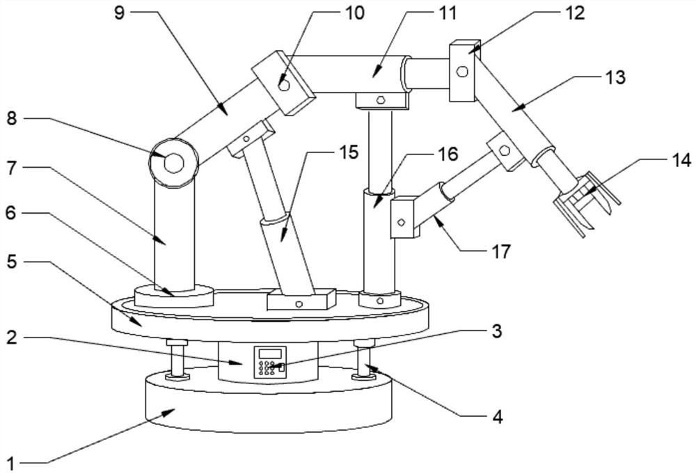
[0021] see Figures 1 to 3 In the embodiment of the present invention, a simple manipulator for an industrial robot includes a fixed base 1; a control box 2 is installed on the top of the fixed base 1; a control panel 3 is arranged on the control box 2; There is a working mechanism 5; the top of the working mechanism 5 is fixedly installed with a fixing table 6; the fixing table 6 is connected to the No. 1 fixing rod 7; The No. 2 fixed rod 9 is connected to the No. 1 electro-hydraulic telescopic rod 11 through the No. 2 installation mechanism 10; One end of the No. 2 electro-hydraulic telescopic rod 13 away from the No. 3 mounting mechanism 12 is movably installed with a mechanical claw 14 .

[0022] Further, the fixed base 1 and the working mechanism 5 are fixedly connected by a fixed rod 4; the setting of the fixed rod 4 increases the stability of the device during operation.

[0023] Further, the control box 2 is communicated with the working mechanism 5; the control box ...

Embodiment 2

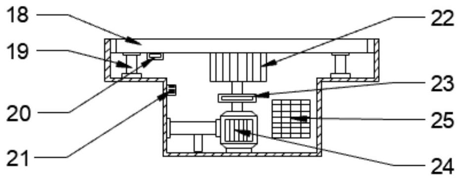
[0028] see figure 2 , a pressure sensor 20 is installed at the bottom end of the rotating disk 18; the pressure sensor 20 is electrically connected to the alarm 21; the alarm 21 is electrically connected to the PLC control circuit board 25; The setting of the PLC control circuit board 25 can prevent the device from being damaged due to excessive pressure when the device is in use.

[0029]The working principle of the present invention is as follows: through the setting of the fixed rod 4, the stability of the device during operation is increased; through the No. 1 driving motor 24, the PLC control circuit board 25, the No. 1 reversing mechanism 23, the gear 22, the rotating disk 18, the support The setting of the rod 19 can adjust the angle of 360 degrees according to the angular relationship between the object and the mechanical claw 14, and the use is more flexible; The setting of the electro-hydraulic telescopic rod 17 can precisely adjust the spatial position of the mech...


PUM


Abstract

The invention discloses a simple manipulator of an industrial robot, which comprises a fixed base; a control box is installed on the top of the fixed base; a control panel is arranged on the control box; a working mechanism is arranged on the top of the control panel; The fixed platform is fixedly installed; the fixed platform is connected to the No. 1 fixed rod; the No. 1 fixed rod is connected to the No. 2 fixed rod through the No. 1 installation mechanism; the No. 2 fixed rod is connected to the No. Hydraulic telescopic rod; the No. 1 electro-hydraulic telescopic rod is connected to the No. 2 electro-hydraulic telescopic rod through the No. 3 installation mechanism; the end of the No. 2 electro-hydraulic telescopic rod far away from the No. 3 installation mechanism is movably installed with a mechanical claw. The invention is flexible and convenient to use and has high safety.

Description

technical field [0001] The invention relates to the technical field of robots, in particular to a simple manipulator of an industrial robot. Background technique [0002] Since the raw materials, intermediate products and final products in industrial production have to go through the process of handling, the handling in the past was mainly by manpower, and some products or raw materials that needed to be handled were in powder form; in this way, on the one hand, the powder would spread In the air, manual handling will endanger human health; on the other hand, the cost of manual handling is high and the efficiency is low; and the packaging shapes of raw materials, intermediate products and final products are different, and different grippers need to be replaced for handling, but the replacement of grippers On the one hand, time is wasted, and on the other hand, the structure of the gripper is complicated. [0003] Therefore, in view of the above status quo, there is an urgen...

Claims


Application Information

Patent Timeline
Patent Type & Authority Patents(China)
IPC IPC(8): B25J15/00B25J19/02B25J19/00B25J19/06B65G47/90
CPCB25J15/00B25J19/02B25J19/00B25J19/06B65G47/90B25J19/061
Inventor 王晓军刘向红钟森鸣
Owner GUANGDONG POLYTECHNIC NORMAL UNIV
Why Eureka
Try Eureka