Ultrasonic high-precision, high-efficiency welding equipment

A welding equipment and high-precision technology, which is applied in the field of high-efficiency welding equipment and ultrasonic high-precision, can solve the problems of affecting welding accuracy, affecting welding speed, and insufficient efficiency

Active Publication Date: 2021-10-08
CHONGQING TECH & BUSINESS UNIV
View PDF5 Cites 0 Cited by
  • Summary
  • Abstract
  • Description
  • Claims
  • Application Information

AI Technical Summary

Problems solved by technology

[0004] The existing ultrasonic welding equipment has the problem that the efficiency is not high enough when welding the metal mesh to the hole of the earphone cover. It needs to be clamped twice and remove the earphone cover, which affects the welding speed; and the position of the earphone cover is not correct after clamping. At the same time, the transducer and the welding torch can only move along the axial direction of the welding torch, and the welding accuracy will be affected when the earphone cover is placed in a deviation

Method used


Image

  • Ultrasonic high-precision, high-efficiency welding equipment
  • Ultrasonic high-precision, high-efficiency welding equipment
  • Ultrasonic high-precision, high-efficiency welding equipment

Examples


Embodiment 1

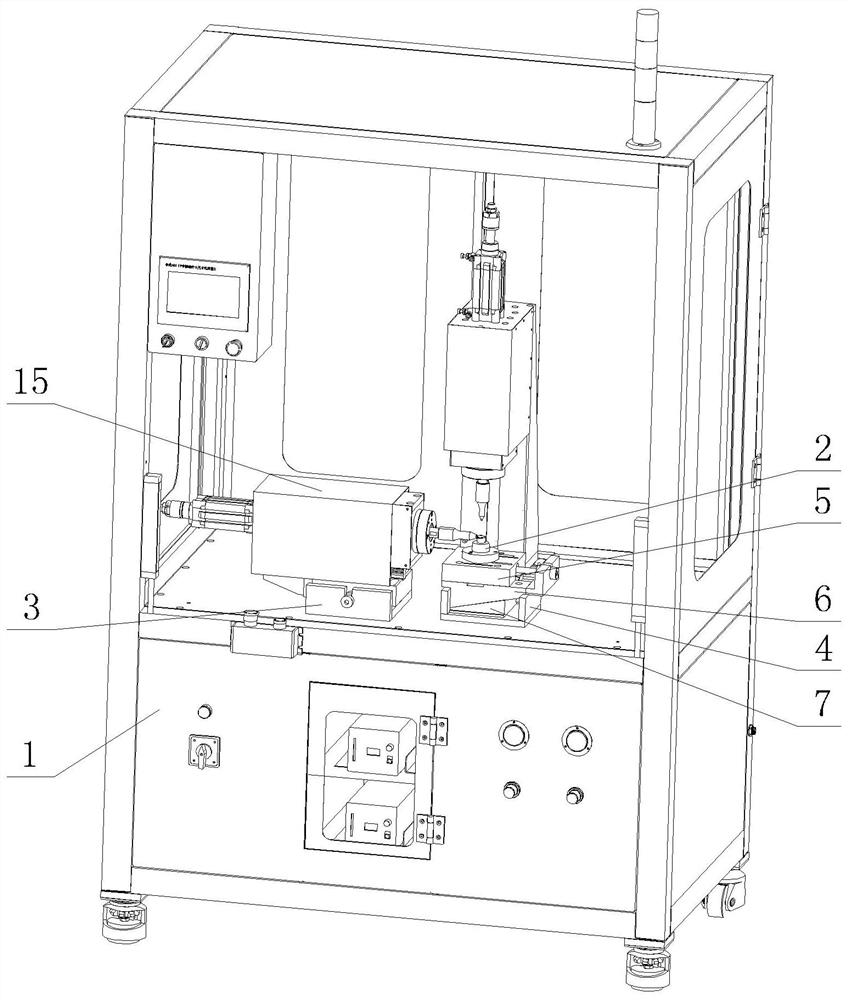
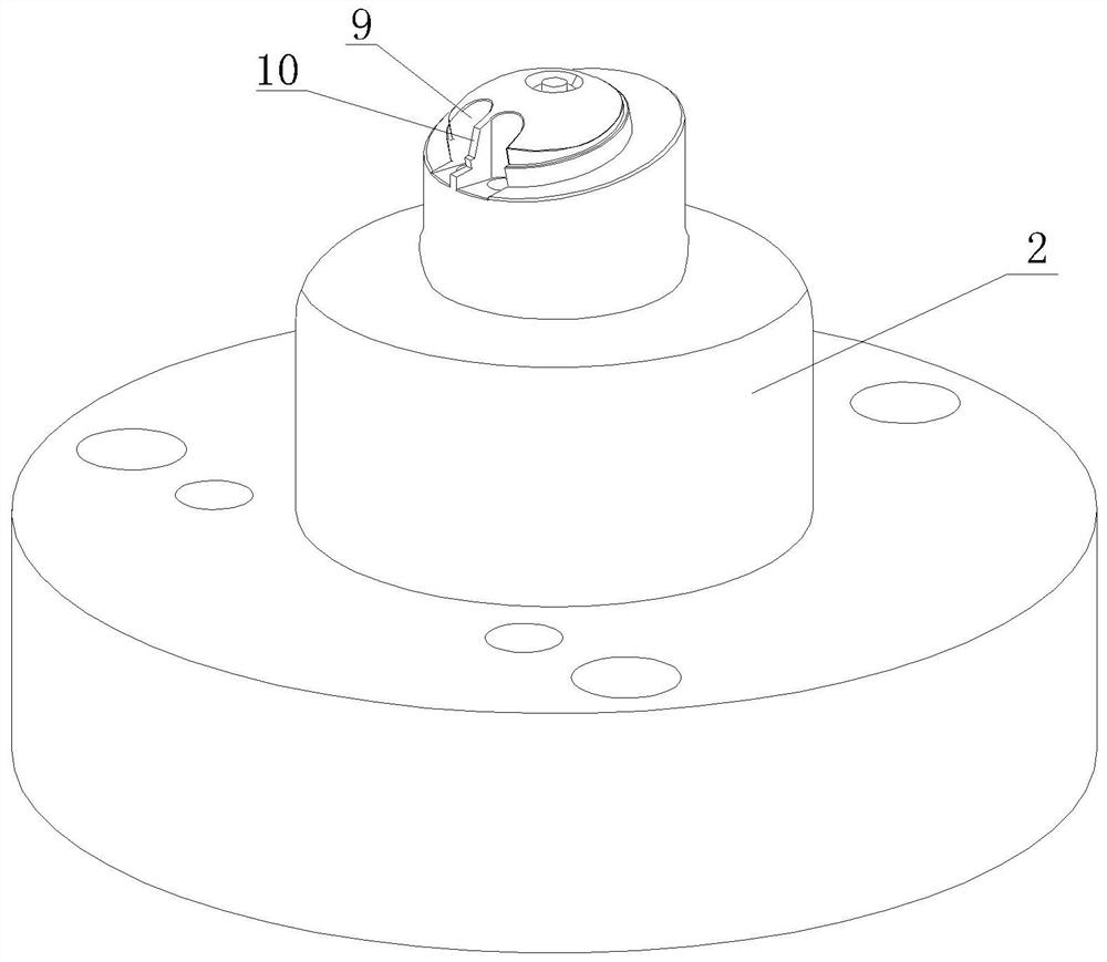
[0025] Embodiment 1 is basically as attached Figure 1-4 Shown: as figure 1 The ultrasonic high-precision and high-efficiency welding equipment shown includes welding cabinet 1, positioning seat 2, positioning seat adjustment assembly and two welding mechanisms; welding cabinet 1 includes upper and lower layers, and the lower layer is mainly used for installing ultrasonic cabinets, pressure reducing valves and For fan etc., the upper stratum is provided with two support seats 3 by screws, and certainly the positioning seat 2, the positioning seat adjustment assembly and two welding mechanisms are also installed on the upper strata.

[0026] The positioning seat adjustment assembly includes a frame body 4, a slide table 5, a bottom block 6 and a slide block 7, the bottom block 6 and the slide block 7 are in the shape of a right-angled trapezoid, and the bottom block 6 and the slide block 7 are all slidably arranged in the frame body 4; The slope of the bottom block 6 contacts ...

Embodiment 2

[0035] The difference from Embodiment 1 is that in this embodiment, the adjusting member includes a screw and a nut. Instead of a threaded hole 21, a through hole is opened on the adjusting fixing seat 20, and the screw rod is slidingly connected with the through hole. ; The left end of the screw rod is hinged with the adjusting pressing piece 19, specifically, a connecting rod in the shape of "]" is welded on the adjusting pressing piece 19, the length direction of the connecting rod points to the center of the adjusting pressing piece 19, and the left end of the screw rod is welded with a connection The connecting ring is sleeved on the connecting rod; the right end of the screw rod can be threadedly connected with the nut after passing through the through hole. When the position of the welding torch 14 and the sounder 12 is adjusted by turning the welding torch 14, the screw rod is locked directly through the nut. Since the nut is located outside the adjustment fixing seat 2...


PUM


Abstract

The invention relates to the field of welding, in particular to ultrasonic high-precision, high-efficiency welding equipment, including a positioning seat, a positioning seat adjustment assembly and two welding mechanisms; each welding mechanism includes a sounder, a transducer, a transducer adjustment assembly and a welding torch , the transducer adjustment assembly includes an adjustment fixing cover, a fixing ring, an adjustment fixing seat and several adjustment parts. The arc surface matched with the inner wall of the adjustable fixed cover, the transducer and the inner wall of the fixed ring have an interference fit, the adjustable fixed seat is fixedly connected with the adjustable fixed cover, and the adjusting member can pass through the adjustable fixed seat to adjust the fixed ring. When the technical solution is adopted, the metal mesh can be welded to the hole of the earphone cover with high precision and high efficiency.

Description

technical field [0001] The invention relates to the field of welding, in particular to ultrasonic high-precision and high-efficiency welding equipment. Background technique [0002] Ultrasonic welding is to use high-frequency vibration waves to transmit to the surfaces of two objects to be welded, so that the surfaces of the two objects rub against each other to form fusion between molecular layers. Welding metal mesh at the earphone cover holes on the front and side of the earphone cover is also used Ultrasonic welding. [0003] The current ultrasonic welding equipment includes a transducer (the core component of the ultrasonic equipment), a welding torch and a support table, the welding torch is connected to the transducer, and the welding torch is located above the support table; the support table is provided with a clamping mechanism for clamping the earphone cover, When it is necessary to weld the metal mesh at the earphone cover hole of the earphone cover, after fixin...

Claims


Application Information

Patent Timeline
Patent Type & Authority Patents(China)
IPC IPC(8): B23K20/10B23K20/26
CPCB23K20/10B23K20/26
Inventor 夏洪均李平李永亮王旭东杨承志
Owner CHONGQING TECH & BUSINESS UNIV
Why Eureka
Try Eureka