A 5m-level weakly rigid tank bottom girth welding equipment

A circular seam welding and weak rigidity technology, applied in the field of storage tank bottom, can solve the problems of weldment deformation, weak rigidity of wall thickness, weak rigidity of large diameter tank bottom, etc., to achieve the effect of ensuring welding positioning accuracy and automatic circular seam welding

Active Publication Date: 2016-06-22
CHINA ACAD OF LAUNCH VEHICLE TECH +2
View PDF9 Cites 0 Cited by
  • Summary
  • Abstract
  • Description
  • Claims
  • Application Information

AI Technical Summary

Problems solved by technology

However, with the continuous increase of the size of the rocket storage tank, the diameter of the tank bottom is also increasing, while the wall thickness of the tank bottom is continuously decreasing, so the rigidity of the large diameter tank bottom is weak
When welding the annular seam between the top cover and the ring, and the annular seam between the ring and the transition ring, due to the thin wall thickness and weak rigidity of the large-diameter box bottom weldment, the positioning of the weldment and the welding process It is easy to cause deformation of the weldment

Method used


Image

  • A 5m-level weakly rigid tank bottom girth welding equipment
  • A 5m-level weakly rigid tank bottom girth welding equipment
  • A 5m-level weakly rigid tank bottom girth welding equipment

Examples


Embodiment Construction

[0020] In order to make the object, technical solution and advantages of the present invention clearer, the present invention will be further described in detail below in conjunction with the accompanying drawings.

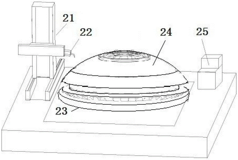
[0021] figure 2 It is a structural schematic diagram of a tank bottom girth seam welding equipment provided by an embodiment of the present invention. Such as figure 2 As shown, the tank bottom girth welding equipment includes: a welding bed 21 , a welding unit 22 , a rotating platform 23 and a welding mold tire 24 .

[0022] The welding bed 21 is fixed on the foundation, and can move along three-dimensional linear degrees of freedom, that is, reciprocate along the X-axis, Y-axis and Z-axis directions. At this time, since the welding unit 22 is arranged on the welding bed 21 , the welding unit 22 can be precisely positioned to any position in the three-dimensional space by adjusting the welding bed 21 .

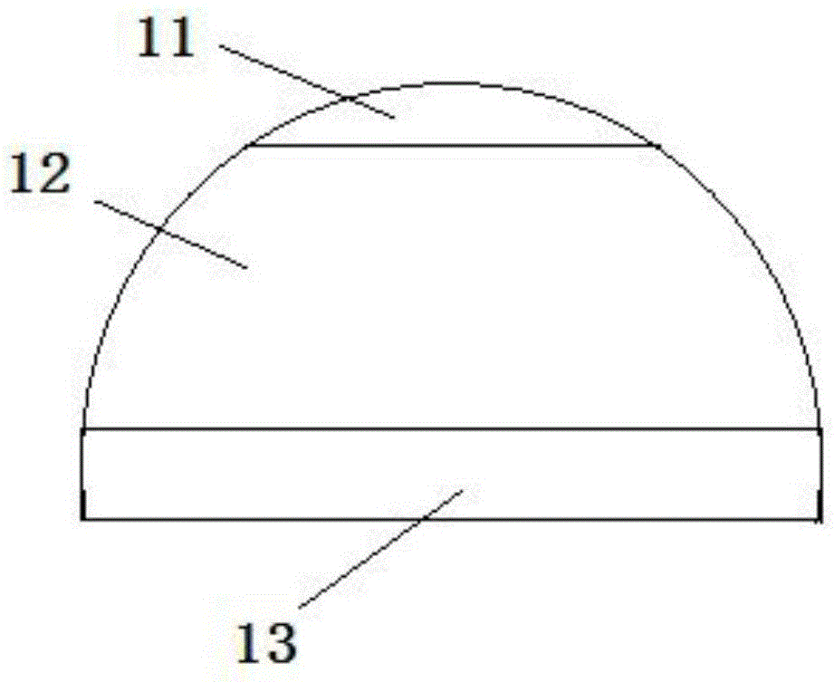
[0023] The top cover, the circular ring and the transi...


PUM


Abstract

The embodiment of the invention provides box bottom circumferential seam welding equipment for a 5M-grade weak-rigidity storage box, which can realize automatic circumferential seam welding of a box bottom of a large-diameter storage box. The box bottom circumferential seam welding equipment comprises a welding bed body (21), a welding unit (22), a rotary platform (23) and a welding die tire (24), wherein the welding bed body (21) can move along the freedom of degree of a three-dimensional straight line; the welding unit (22) is arranged on the welding bed body (21); the welding die tire (24) is arranged on the rotary platform (23) and can do plane rotation and vertical overturning along the rotary platform (23).

Description

technical field [0001] The invention relates to the tank bottom technology, in particular to a 5M-level weakly rigid tank bottom ring seam welding equipment. Background technique [0002] figure 1 It is a schematic diagram of the structure of the tank bottom. Such as figure 1 As shown, the bottom of the rocket tank is hemispherical and is welded by the top cover 11, the ring 12 and the transition ring 13. However, with the continuous increase of the size of the rocket storage tank, the diameter of the bottom of the tank is also continuously increased, while the wall thickness of the bottom of the tank is continuously reduced, so the rigidity of the large diameter tank bottom is weak. When welding the annular seam between the top cover and the ring, and the annular seam between the ring and the transition ring, due to the thin wall thickness and weak rigidity of the large-diameter box bottom weldment, the positioning of the weldment and the welding process It is easy to c...

Claims


Application Information

Patent Timeline
Patent Type & Authority Patents(China)
IPC IPC(8): B23K37/04B23K37/047B23K37/02
CPCB23K37/0211B23K37/0443B23K37/047
Inventor 孟凡新王国庆高培涛孔德跃杜岩峰张中平张蓬田超
Owner CHINA ACAD OF LAUNCH VEHICLE TECH
Why Eureka
Try Eureka