Pallet calibration device and method

A technology of a calibration device and a calibration method, which is applied in the direction of a lifting device, etc., can solve problems such as limited tray guide angle, abnormal displacement of the tray, and limited limit range, so as to avoid damage to the tray, improve calibration efficiency, and ensure calibration accuracy. Effect

Active Publication Date: 2020-11-10
NOBLEELEVATOR INTELLIGENT EQUIP CO LTD +1
View PDF8 Cites 0 Cited by
  • Summary
  • Abstract
  • Description
  • Claims
  • Application Information

AI Technical Summary

Problems solved by technology

[0005] 2. Consistency and precision differences of multiple AGV forklifts;
[0006] 3. Accumulated error of repeated pallet handling;
[0007] 4. Abnormal displacement of the tray;
[0014] 1. High requirements for manual placement and reduced placement efficiency
[0015] 2. Damage the tray, because it is a mechanical hard impact, the contact sound is loud, the tray is damaged, and the life is reduced;
[0016] 3. Damage to the limit structure. Due to mechanical collision, the limit structure is repeatedly scratched, and damage and paint peeling will occur to varying degrees several times;
[0017] 4. The limit range is limited, because the height of the pallet is fixed and the guiding angle of the pallet is limited, so the guiding range is limited;
[0018] 5. The limit accuracy is limited because the limit structure cannot be moved. In order to ensure that the pallet can be taken out smoothly, the limit structure has a certain gap with the pallet in theory;
[0019] 6. There are potential safety hazards. First: Once the vehicle exceeds the limit precision in the way of falling, the goods cannot slide down, and the pallet is stuck on the limit structure, which can easily cause potential safety hazards. Second: Once the vehicle enters the way beyond the limit precision, The pallet will hit the limit structure, the pallet will be damaged, and the material will be damaged

Method used


Image

  • Pallet calibration device and method
  • Pallet calibration device and method
  • Pallet calibration device and method

Examples


Embodiment 1

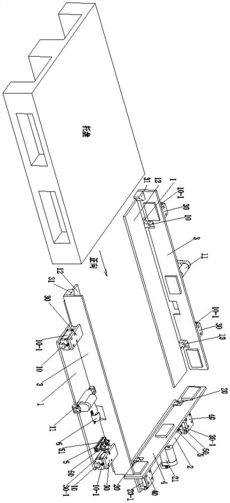
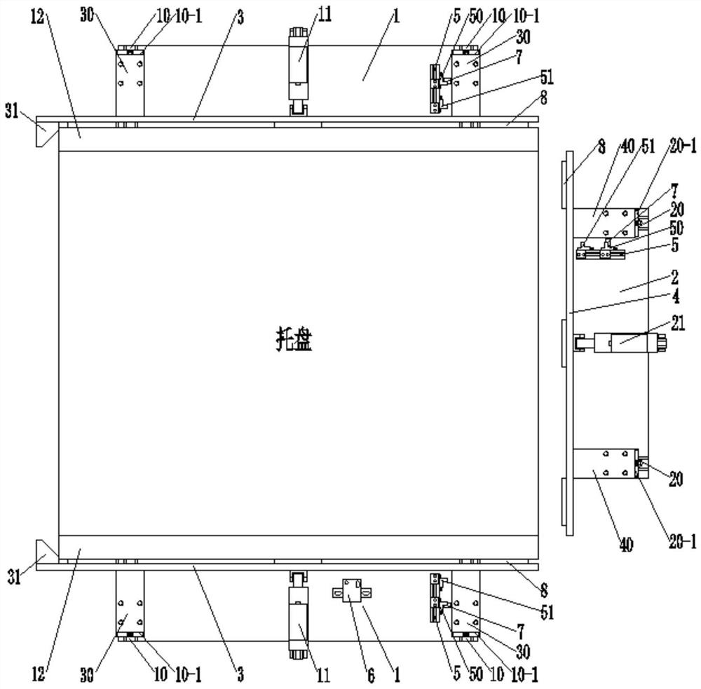
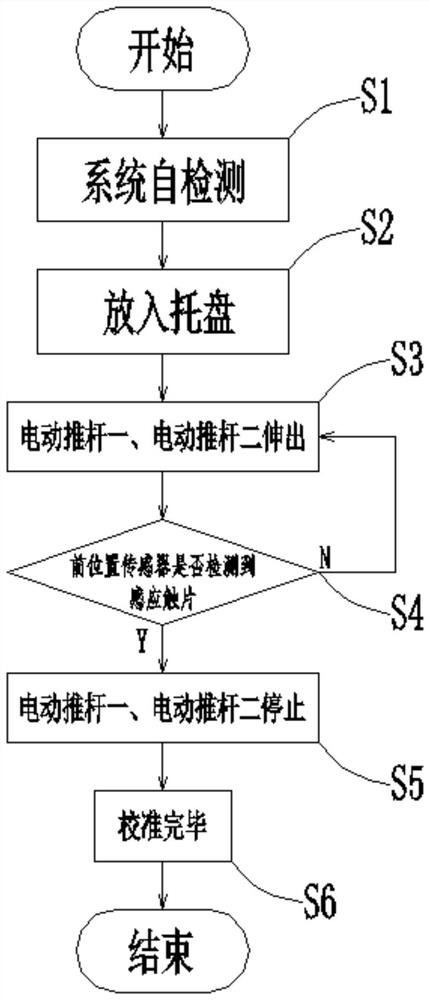
[0078] First, the system performs a self-inspection to determine whether the rear position sensor 50 of the tray calibration device detects the sensing contact piece 7. If so, it proves that the electric push rod one 11 and the electric push rod two 21 shrink to the rear, that is, the two side push plates 3 and A positive push plate 4 is in a shrinking state, and then it is judged whether an object is detected by the seat switch 6. If so, the alarm system is turned on to give an alarm, prompting the staff that there is an object placed in the tray calibration device, and if not, the tray is calibrated. Place the tray in the unit.

[0079] Then electric push rod one 11, electric push rod two 21 stretch out, until connecting plate one 30 and connecting plate two 40 are provided with induction contact sheet 7 and stop at front position sensor 51, and now the pallet position calibration is completed.

Embodiment 2

[0081] On the basis of Example 1, a plurality of rubber pads 8 are provided on the inner walls of the side push plate 3 and the forward push plate 4, which avoids contact between the tray and the inside of the two side push plates 3 and one forward push plate 4. , to avoid damage to the pallet and pallet alignment device.

[0082] A nylon plate 12 is provided inside the bottom plate 1 to reduce the frictional resistance on the bottom of the tray and avoid damage to the tray.

[0083] The entrance of the side push plate 3 is provided with a nylon guide block 31, and the cut angle of the nylon guide block 31 is less than or equal to 45°, so that when the two side push plates 3 are calibrating the position of the tray, the nylon guide block 31 will also move the tray Push it inward to ensure that the positive push plate 4 also plays the role of pallet position calibration.

Embodiment 3

[0085] In the pallet calibration method of the present invention, system detection is performed before calibration, avoiding false detection and safety accidents, and the system responds quickly and has a high degree of automation.

[0086] A pallet calibration method of the present invention can also perform position calibration on containers with other rectangular frames; and by changing the shape of the inner walls of the side push plate 3 and the forward push plate 4, it can be adapted to the calibration operation of containers with other shapes.


PUM


Abstract

Manual placement errors, damage to pallets and potential safety hazards are avoided, and the calibration efficiency is improved; the service life of the pallets is ensured; the pallet limiting range is widened to achieve adaptation to the pallets of different sizes; limiting precision adjustment is achieved; and the precision butt joint requirements of other robots are met. The invention disclosesa pallet calibration device and method. The pallet calibration device comprises first bottom plates, a second bottom plate, side push plates, a front push plate, limiting switch bases and on-site switches. First guide rails are arranged on the two sides of each first bottom plate in parallel, first sliding blocks are slidably arranged on the first guide rails, a first electric push rod is arranged in the middle of each first bottom plate, and the push rod end of each first electric push rod is hinged to the middle of the corresponding side push plate; second guide rails are arranged on the two sides of the second bottom plate in parallel, second sliding blocks are slidably arranged on the second guide rails, a second electric push rod is arranged in the middle of the second bottom plate,and the push rod end of the second electric push rod is hinged to the middle of the front push plate; the side push plates are provided with first connecting plates; the front push plate is provided with second connecting plates; and the limiting switch bases are connected with the first bottom plates and the second bottom plate correspondingly, and the on-site switches are connected with the first bottom plates.

Description

technical field [0001] The invention belongs to the technical field of industrial vehicles with automatic guidance function, in particular, the invention relates to a pallet calibration device and method. Background technique [0002] AGV refers to a transport vehicle equipped with automatic navigation devices such as electromagnetic or optical, capable of driving along a prescribed navigation path, with safety protection and various transfer functions. A truck that does not require a driver in industrial applications is powered by a rechargeable battery. Generally, the computer can be used to control its travel path and behavior, or the electromagnetic track can be used to set up its travel path. The electromagnetic track is pasted on the floor, and the unmanned van relies on the information brought by the electromagnetic track to move and move. [0003] AGV is a new technology product, which has high requirements on safety and must obtain the status of the vehicle at all ...

Claims


Application Information

Patent Timeline
Patent Type & Authority Applications(China)
IPC IPC(8): B66F9/075B66F9/24
CPCB66F9/075B66F9/24
Inventor 佐富兴樊雨周晓静张小健杨方兵刘杰朱婷婷
Owner NOBLEELEVATOR INTELLIGENT EQUIP CO LTD
Why Eureka
Try Eureka