Network transformer splitting device

A technology of network transformer and material distribution device, which is applied in inductance/transformer/magnet manufacturing, sorting, electrical components and other directions, can solve problems such as increasing production cost, placing errors, reducing production efficiency, etc. material, avoid the effect of placing errors

Pending Publication Date: 2017-12-01
LEIYANG YAXIANG ELECTRONICS TECH
View PDF6 Cites 2 Cited by
  • Summary
  • Abstract
  • Description
  • Claims
  • Application Information

AI Technical Summary

Problems solved by technology

[0003] The existing network transformer distributing device often adopts the manual distributing method, that is, according to the results of visual inspection, the qualified and unqualified network transformers are manually placed separately. On the one hand, the production efficiency is reduced and the production cost is increased; on the other hand , with serving errors

Method used


Image

  • Network transformer splitting device
  • Network transformer splitting device
  • Network transformer splitting device

Examples


Embodiment Construction

[0023] In order to facilitate the understanding of those skilled in the art, the present invention will be further described below in conjunction with the embodiments and accompanying drawings, and the contents mentioned in the embodiments are not intended to limit the present invention.

[0024] In describing the present invention, it is to be understood that the terms "upper", "lower", "front", "rear", "left", "right", "vertical", "horizontal", "top", The orientation or positional relationship indicated by "bottom", "inner", "outer", etc. is based on the orientation or positional relationship shown in the drawings, and is only for the convenience of describing the present invention and simplifying the description, rather than indicating or implying the referred device Or elements must have a certain orientation, be constructed and operate in a certain orientation, and thus should not be construed as limiting the invention.

[0025] In the description of the present invention...


PUM


Abstract

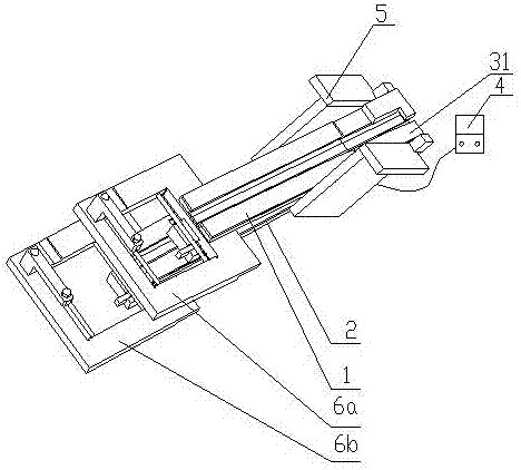
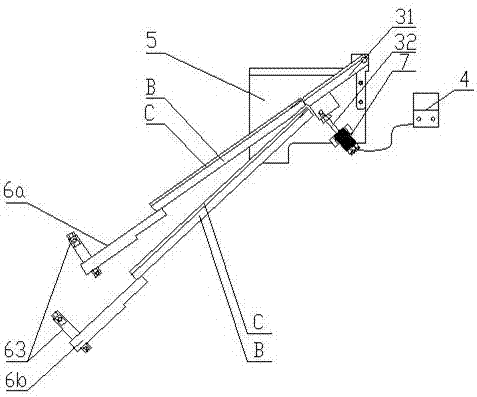
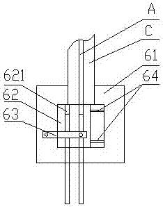
The invention discloses a network transformer splitting device and relates to the technical field of electronic component machining. The network transformer splitting device comprises a good product receiving channel, a defective product receiving channel, a reversing mechanism and two vertical mounting boards; the reversing mechanism comprises a reversing channel and a telescopic rod; one end of the telescopic rod is movably connected with the bottom face of the reversing channel; the head end of the reversing channel is hinged between the two mounting boards; the tail end of the reversing channel is connected with the head end of the good product receiving channel when the telescopic rod stretches out; a good product receiving opening is formed in the tail end of the good product receiving channel; the tail end of the reversing channel is connected with the head end of the defective product receiving channel when the telescopic rod draws back; a defective product receiving opening is formed in the tail end of the defective product receiving channel; and the good product receiving channel and the defective product receiving channel are fixed between the two mounting boards up and down and spaced by a certain distance. The network transformer splitting device achieves the rapid and accurate splitting function.

Description

technical field [0001] The invention relates to the technical field of electronic component processing, in particular to a network transformer material distributing device. Background technique [0002] When designing routers and switches, we will use a very commonly used device between the Ethernet PHY chip and the RJ45 interface - a network transformer, also known as data mercury. The main functions of the network transformer are signal transmission, impedance matching, waveform repair, signal clutter suppression and voltage isolation, etc. During its production process, its pins are handled very strictly, because the pins are easy to bend, and after bending The failure of the pins to meet the installation standards will affect the normal use of the network transformer. Therefore, visual inspection and material separation are required before the network transformer is produced and packaged. The qualified products and unqualified defective products are stored separately. Th...

Claims


Application Information

Patent Timeline
Patent Type & Authority Applications(China)
IPC IPC(8): B07C5/36H01F41/00
CPCH01F41/00B07C5/361
Inventor 陈小勇龚亮杨艳军朱千林
Owner LEIYANG YAXIANG ELECTRONICS TECH
Why Eureka
Try Eureka