Tray linkage calibration device and method

A technology of calibration device and calibration method, which is applied in the direction of lifting device, etc., can solve the problems of loud contact sound, limited limit range, and goods cannot slide down, etc., achieve the effect of low calibration contact sound, ensure calibration accuracy, and avoid potential safety hazards

Pending Publication Date: 2020-11-10
NOBLEELEVATOR INTELLIGENT EQUIP CO LTD +1
View PDF0 Cites 0 Cited by
  • Summary
  • Abstract
  • Description
  • Claims
  • Application Information

AI Technical Summary

Problems solved by technology

[0005] 2. Consistency and precision differences of multiple AGV forklifts;
[0006] 3. Accumulated error of repeated pallet handling;
[0007] 4. Abnormal displacement of the tray;
[0014] 1. High requirements for manual placement and reduced placement efficiency
[0015] 2. Damage the tray, because it is a mechanical hard impact, the contact sound is loud, the tray is damaged, and the life is reduced;
[0016] 3. Damage to the limit structure. Due to mechanical collision, the limit structure is repeatedly scratched, and damage and paint peeling will occur to varying degrees several times;
[0017] 4. The limit range is limited, because the height of the pallet is fixed and the guiding angle of the pallet is limited, so the guiding range is limited;
[0018] 5. The limit accuracy is limited because the limit structure cannot be moved. In order to ensure that the pallet can be taken out smoothly, the limit structure has a certain gap with the pallet in theory;
[0019] 6. There are potential safety hazards. First: Once the vehicle exceeds the limit precision in the way of falling, the goods cannot slide down, and the pallet is stuck on the limit structure, which can easily cause potential safety hazards. Second: Once the vehicle enters the way beyond the limit precision, The pallet will hit the limit structure, the pallet will be damaged, and the material will be damaged

Method used


Image

  • Tray linkage calibration device and method
  • Tray linkage calibration device and method
  • Tray linkage calibration device and method

Examples


Embodiment 1

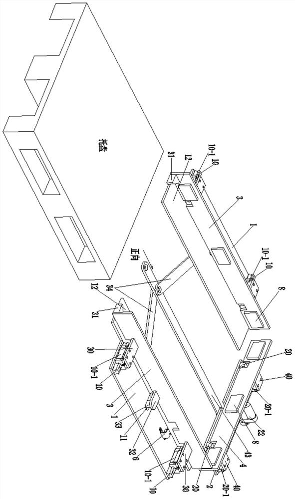
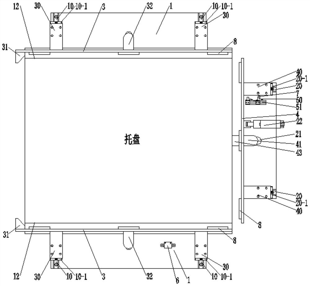
[0082] First, the system performs a self-inspection to determine whether the rear position sensor 50 of the tray calibration device detects the sensing contact piece 7. If so, it proves that the electric push rod 22 is retracted to the rear, that is, the two side push plates 3 and one forward push plate 4 are in contraction. state, and then judge whether the seat switch 6 detects an object, if so, the alarm system is turned on and reports to the police, prompting the staff to place an object in the tray calibration device, if not, then put into the tray in the tray calibration device.

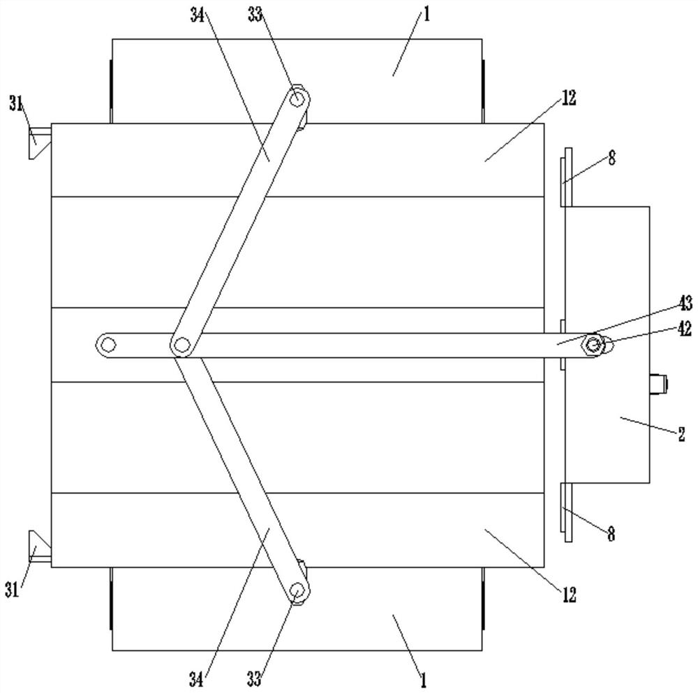
[0083] Then the electric push rod 22 stretches out, and the forward push plate 4 is released under the guidance of the guide rail 20, and at the same time, the extension plate 41 provided on the back side of the forward push plate 4 pushes the connecting rod 2 43 out through the limit shaft 42 , at this moment, connecting rod 2 43 pushes two connecting rods 1 34 forward, so that the included ang...

Embodiment 2

[0086] On the basis of Example 1, a plurality of rubber pads 8 are provided on the inner walls of the side push plate 3 and the forward push plate 4, which avoids contact between the tray and the inside of the two side push plates 3 and one forward push plate 4. , to avoid damage to the pallet and pallet alignment device.

[0087] A nylon plate 12 is provided inside the bottom plate 1 to reduce the frictional resistance on the bottom of the tray and avoid damage to the tray.

[0088] The entrance of the side push plate 3 is provided with a nylon guide block 31, and the cut angle of the nylon guide block 31 is less than or equal to 45°, so that when the two side push plates 3 are calibrating the position of the tray, the nylon guide block 31 will also move the tray Push it inward to ensure that the positive push plate 4 also plays the role of pallet position calibration.

Embodiment 3

[0090] In the pallet linkage calibration method of the present invention, system detection is performed before calibration, avoiding false detection and safety accidents, and the system responds quickly and has a high degree of automation.

[0091] The tray linkage calibration method of the present invention can also perform position calibration on other rectangular-framed containers; and by changing the inner wall shape of the side push plate 3 and the forward push plate 4, it can be adapted to the calibration operation of containers with other shapes.


PUM


Abstract

The invention discloses a tray linkage calibration device and method. The tray linkage calibration device comprises a first bottom plate, a second bottom plate, a side push plate, a front push plate,a limiting switch base and an in-seat switch. A first guide rail is arranged on the first bottom plate, and a first limiting hole is formed in the middle of the first bottom plate; a second guide railis arranged on the second bottom plate, a second limiting hole is formed in the second bottom plate, and an electric push rod is arranged on the second bottom plate; the side push plate is provided with a first connecting plate; the front push plate is provided with a second connecting plate; the limit switch base is connected with the second bottom plate, and the in-seat switch is connected withthe first bottom plate; the side push plate is provided with a first extension plate, a limiting pin is arranged at the lower end of the first extension plate, and first connecting rods are hinged tothe lower end of the limiting pin; the front push plate is provided with a second extension plate, a limiting shaft is arranged at the lower end of the second extension plate, and the lower end of the limiting shaft is connected with a second connecting rod; and one end part of each of the two first connecting rods is hinged with the second connecting rod. Manual placement errors, tray damage andpotential safety hazards are avoided, and the calibration efficiency is improved; the service life of a tray is ensured; the limiting range of the tray is expanded; the limiting precision adjustmentis realized; and the precision butt joint requirements of other robots are met.

Description

technical field [0001] The invention belongs to the technical field of industrial vehicles with automatic guidance function, in particular, the invention relates to a pallet linkage calibration device and method. Background technique [0002] AGV refers to a transport vehicle equipped with automatic navigation devices such as electromagnetic or optical, capable of driving along a prescribed navigation path, with safety protection and various transfer functions. A truck that does not require a driver in industrial applications is powered by a rechargeable battery. Generally, the computer can be used to control its travel path and behavior, or the electromagnetic track can be used to set up its travel path. The electromagnetic track is pasted on the floor, and the unmanned van relies on the information brought by the electromagnetic track to move and move. [0003] AGV is a new technology product, which has high requirements on safety and must obtain the status of the vehicle...

Claims


Application Information

Patent Timeline
IPC IPC(8): B66F9/075B66F9/24
CPCB66F9/075B66F9/24
Inventor 樊雨佐富兴刘杰包锦超吴维平周晓静朱婷婷
Owner NOBLEELEVATOR INTELLIGENT EQUIP CO LTD
Why Eureka
Try Eureka