Eureka AIR delivers breakthrough ideas for toughest innovation challenges, trusted by R&D personnel around the world.

Wall plastering slurry throwing tool

A technology of throwing pulp and tools, which is applied in the direction of construction and building construction, and can solve the problems of workers' arm pain, waste, and uneven throwing of pulp, etc.

Inactive Publication Date: 2020-11-10
ZHEJIANG WANHUA CONSTR
View PDF6 Cites 2 Cited by
  • Summary
  • Abstract
  • Description
  • Claims
  • Application Information

AI Technical Summary

Problems solved by technology

[0003] In the existing construction process, generally use a slurry slap made of steel wire to slap the wall directly, so that the cement slurry at one end of the steel mesh passes through the slap and slaps it onto the wall, but the workers need to continuously use the slurry to slap the wall. The worker's arms are prone to soreness, and the slurry batter cannot evenly contact the wall, resulting in uneven slurry. When the wall is slapped, under the action of gravity, the cement slurry flows downward in the slurry batt, making the slurry at the bottom of the slurry batt If there is a lot of cement slurry, there will be less cement slurry on the top of the slurry racket, and the slurry will be thrown unevenly. When beating the indoor roof, the cement slurry will be located on the bottom surface of the slurry racket at this time, causing the cement slurry on the slurry racket to drip on the ground. up, wasteful

Method used


Image

  • Wall plastering slurry throwing tool
  • Wall plastering slurry throwing tool
  • Wall plastering slurry throwing tool

Examples


Embodiment Construction

[0024] The present invention will be further described below in conjunction with the accompanying drawings and embodiments.

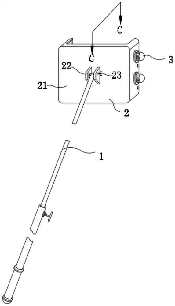
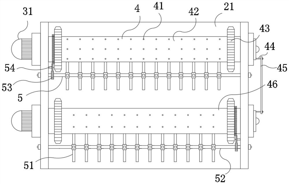
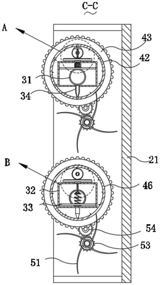
[0025] Please refer to figure 1 , figure 2 , image 3 , Figure 4 , Figure 5 , Figure 6 , Figure 7 and Figure 8 ,in figure 1 A schematic structural view of a preferred embodiment of the wall plastering and slurry throwing tool provided by the present invention; figure 2 It is a schematic diagram of the shell structure shown in Figure 1; image 3 for figure 1 The C-C structure sectional view shown; Figure 4 for image 3 The enlarged schematic diagram of the structure at A shown; Figure 5 for image 3 The enlarged schematic diagram of the structure at B shown; Figure 6 for figure 1 The measured view of the shell structure shown; Figure 7 for figure 1 The schematic diagram of the fixed block structure shown; Figure 8 It is a schematic diagram of the ratchet structure shown in Figure 2. The wall plastering and pulping tool inc...


PUM


Abstract

The invention provides a wall plastering slurry throwing tool. The wall plastering slurry throwing tool comprises a supporting rod, a connecting mechanism, a feeding mechanism, a spraying mechanism and an accelerating mechanism, wherein the spraying mechanism comprises through holes, a first roller, ratchet wheels, a limiting rod, a rotating rod and a second roller, the two ends of the first roller and the two ends of the second roller are fixedly connected with the ratchet wheels, and the through holes are formed in the side wall of the first roller and the side wall of the second roller at equal intervals; the limiting rod is installed at one end of the first roller and one end of the second roller, and the limiting rod is rotationally connected with the rotating rod; the accelerating mechanism comprises scrapers, a fixing shaft, a first gear and a second gear, the multiple scrapers with the arc-shaped side walls are symmetrically installed on the side wall of the fixing shaft, and the elastic scrapers are slidably connected with the first roller, the second roller and the through holes. The tool further comprises a driving mechanism. The wall plastering slurry throwing tool hasthe advantages that slurry throwing is uniform, the labor amount of people is reduced, and cement slurry waste is avoided.

Description

technical field [0001] The invention relates to the technical field of wall plastering and grouting, in particular to a wall plastering and grouting tool. Background technique [0002] In the building construction, after the wall is built, the grout is thrown. The grout is thrown on the wall evenly according to a certain water-binder ratio. After reaching a certain strength, it is plastered. The purpose is to improve the quality of the plastered cement. Adhesion of grout to wall. [0003] In the existing construction process, generally use a slurry slap made of steel wire to slap the wall directly, so that the cement slurry at one end of the steel mesh passes through the slap and slaps it onto the wall, but the workers need to continuously use the slurry to slap the wall. The worker's arms are prone to soreness, and the slurry batter cannot evenly contact the wall, resulting in uneven slurry. When the wall is slapped, under the action of gravity, the cement slurry flows dow...

Claims


Application Information

Patent Timeline
Patent Type & Authority Applications(China)
IPC IPC(8): E04F21/00E04F21/08
CPCE04F21/00E04F21/08
Inventor 韩玉德乐定良柯哲昌赵伟军李科军崔朝赟王振华李银囤刘锋
Owner ZHEJIANG WANHUA CONSTR
Why Eureka
Eureka Blog
Learn More