
Air conditioner

A technology for air conditioning and air conditioning systems, applied to compressors with reversible cycles, lighting and heating equipment, refrigerators, etc., can solve problems such as time delays and reduce the service life of compressors, and achieve the goal of avoiding service life and shortening waiting time Effect

Inactive Publication Date: 2020-11-10
ZHUHAI HUAYU METAL
View PDF8 Cites 0 Cited by
  • Summary
  • Abstract
  • Description
  • Claims
  • Application Information

AI Technical Summary

Problems solved by technology

[0004] The purpose of the present invention is to provide an air conditioner to solve the problem that the compressor in the existing air conditioner needs to wait for a period of time before it can be restarted after being shut down, which leads to time delay and the problem that the service life of the compressor is reduced due to the compressor starting immediately after shutting down

Method used


Image

  • Air conditioner
  • Air conditioner
  • Air conditioner

Examples


Embodiment 1

[0043] This embodiment provides an air conditioner, which is used to solve the problem that the compressor in the existing air conditioner needs to wait for a period of time before it can be restarted after being shut down, which causes time delay, and the service life of the compressor is reduced due to the compressor being started immediately after shutting down. question.

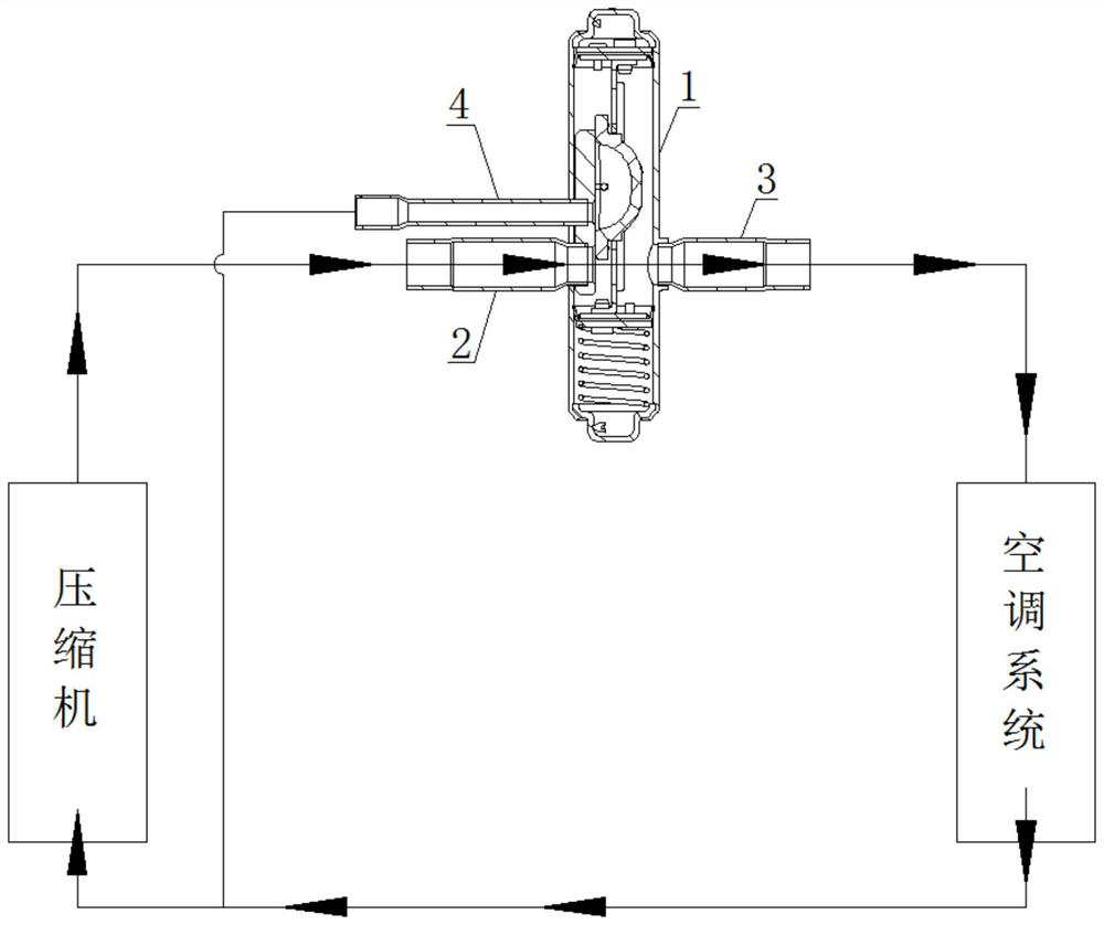
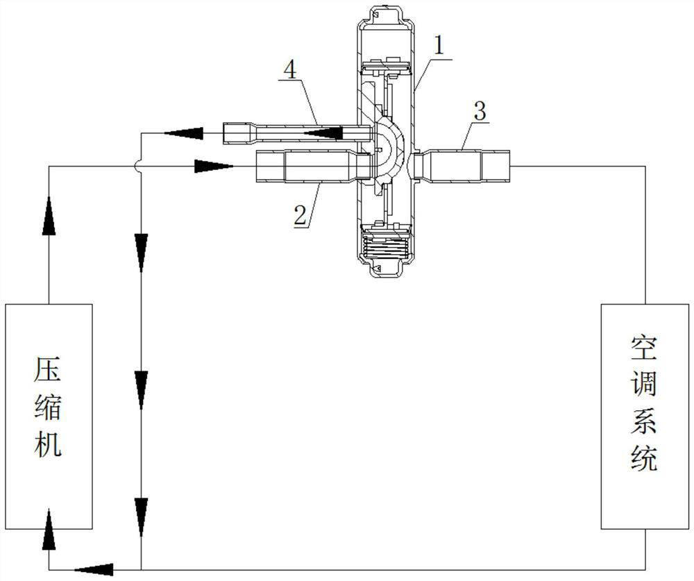
[0044] refer to Figure 1-2 , The air conditioner includes a compressor, an air conditioning system and an electromagnetic three-way valve.

[0045] Wherein, the three-way of the electromagnetic three-way valve is inlet, outlet one and outlet two respectively. The inlet, the outlet one and the outlet two can all be circular holes, which are not shown in the figure. The inlet communicates with the discharge port of the compressor. Outlet one communicates with the input end of the air conditioning system, and the output end of the air conditioning system communicates with the suction port of the compres...

Embodiment 2

[0053] In this embodiment, the structure of the electromagnetic three-way valve in Embodiment 1 is specifically described.

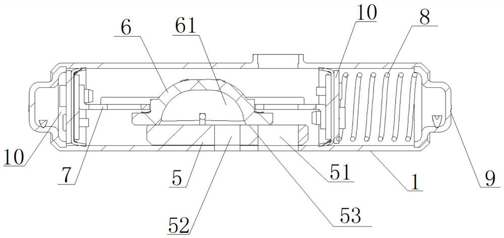
[0054] refer to Figure 3-4 , The electromagnetic three-way valve includes a valve body 1, a valve seat 5, a slider 6, a guide frame 7, an elastic element 8, an end cover 9, a piston 10 and a driving mechanism.

[0055] Wherein, the valve body 1 can be in the shape of a round tube and is a hollow structure. The inlet, the first outlet and the second outlet can all be set on the side wall of the valve body 1 . The inlet and outlet—may be located on opposite sides of the valve body 1 . The inlet and outlet two can be located on the same side of the valve body 1 . The two end caps 9 are installed on opposite ends of the valve body 1 respectively, so that the valve body 1 forms a closed valve cavity.

[0056] The valve seat 5 is accommodated in the valve body 1 and fixed on the inner wall of the valve body 1 having the outlet 2, and two through holes 51 ...


PUM


Abstract

The invention discloses an air conditioner. The air conditioner comprises a compressor, an air conditioning system and an electromagnetic three-way valve. Three ways of the electromagnetic three-way valve are an inlet, a first outlet and a second outlet. The inlet communicates with an exhaust port of the compressor; the first outlet communicates with the input end of the air conditioning system, and the output end of the air conditioning system communicates with an air suction port of the compressor; and the second outlet communicates with the air suction port of the compressor. When the compressor is stopped, the pressure difference between the exhaust port and the air suction port of the compressor is balanced, the compressor can be immediately started again after being stopped, and thewaiting time is greatly shortened.

Description

technical field [0001] The invention relates to the field of air conditioners, in particular to an air conditioner. Background technique [0002] At present, many kinds of automatic reversing valves have been applied in air conditioners to realize the flow switching between refrigerant and heat medium in the air conditioner. For example, the application number is 201120323333.X, a slide valve type self-operated three-way reversing valve, which arranges the compressor connecting pipe above the slide block. When the compressor is started, the inlet airflow is taken over by the compressor and pressed to the slider to reduce the leakage of the slider during movement, so that the heat pipe / vapor compression composite refrigeration and air-conditioning unit has better energy-saving effect and higher reliability. Another example is the four-way electromagnetic reversing valve for a DC inverter air conditioner with the notification number CN2442055Y, which has a simple structure an...

Claims


Application Information

Patent Timeline
Patent Type & Authority Applications(China)
IPC IPC(8): F25B13/00
CPCF25B13/00F25B2313/02731
Inventor 赵豪田卫红
Owner ZHUHAI HUAYU METAL
Learn More